
Heat exchanger and bell-type furnace with same

A heat exchanger and heat exchange cavity technology, applied in the field of bell jar furnaces, can solve the problems of raising the threshold for use of experimental bell jar furnaces, increasing the use cost and the like

Pending Publication Date: 2021-04-27
HUNAN JINLU TECH CO LTD
View PDF0 Cites 3 Cited by
  • Summary
  • Abstract
  • Description
  • Claims
  • Application Information

AI Technical Summary

Problems solved by technology

However, the bell furnace is a complex thermal system integrating temperature, atmosphere, and pressure. Not only the furnace body includes multiple systems such as heating system, atmosphere system, cooling system, and control system, but also additional cooling towers and tracks And other auxiliary systems, which will undoubtedly increase the cost of use and increase the threshold for users to use experimental bell furnaces, especially for the majority of scientific research institutes.

Method used


Image

  • Heat exchanger and bell-type furnace with same
  • Heat exchanger and bell-type furnace with same
  • Heat exchanger and bell-type furnace with same

Examples


Embodiment 1

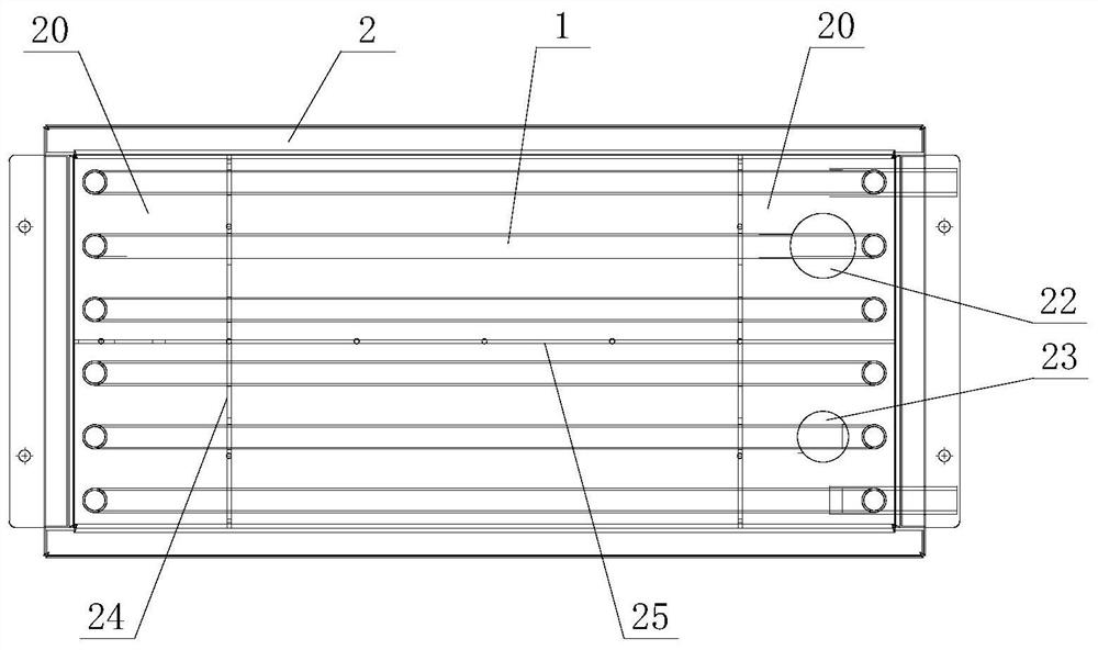
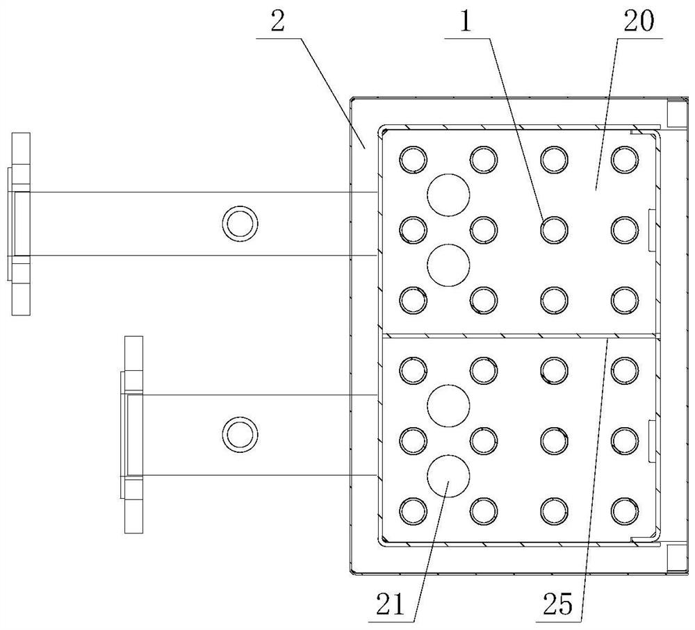
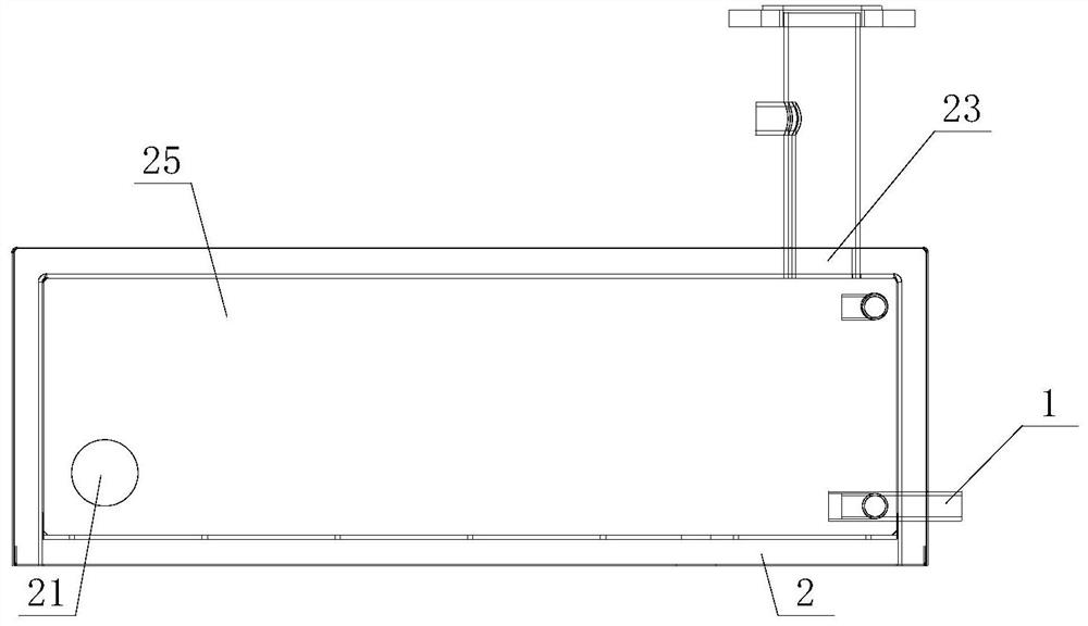
[0028] Such as Figure 1 to Figure 3 As shown, the heat exchanger of this embodiment includes a shell 2 and a water-cooled pipeline 1 for cooling water to pass through. The shell 2 has a heat exchange chamber for gas to pass through. The heat exchange chamber is divided into a plurality of air chambers 20. The two air chambers 20 communicate with each other through communication holes 21, and the housing 2 is provided with an air inlet 22 communicating with one of the air chambers 20 and an air outlet 23 communicating with the other air chamber 20, through which the water cooling pipe 1 passes. At least two air chambers 20 . When the heat exchanger works, the cooling water passes through the water-cooling pipeline 1, and the gas to be cooled is passed into the heat exchange chamber from the air inlet 22, and the gas to be cooled is discharged from the gas outlet 23 through the heat exchange chamber. The pipes 1 are in contact with each other for heat exchange, so as to achiev...

Embodiment 2

[0037] Such as Figure 4 and Figure 5 As shown, a bell furnace includes a furnace body 3, a kiln car 4, a heating system, an air intake system and a cooling system 5, and the cooling system 5 includes a fan 51, a water cooler 52 and the heat exchanger in Embodiment 1, and further The gas port 22 communicates with the hearth of the furnace body 3 through the air inlet pipeline 53, the gas outlet 23 communicates with the furnace hearth of the furnace body 3 through the gas outlet pipeline 54, the two ends of the water cooling pipeline 1 are connected with the water cooler 52, and the fan 51 is arranged on the gas outlet on road 54. When the blower fan 51 starts, the gas in the furnace is allowed to enter the heat exchange chamber of the heat exchanger through the inlet pipeline 53 and the air inlet 22 for cooling, and then returns to the furnace through the gas outlet 23, the blower fan 51 and the gas outlet pipeline 54 after cooling. The cooling system 5 of the bell furnace ...


PUM


Abstract

The invention discloses a heat exchanger and a bell-type furnace with the same. The heat exchanger comprises a shell and a water cooling pipeline for allowing cooling water to pass through, the shell is provided with a heat exchange cavity for allowing gas to pass through, the heat exchange cavity is divided into a plurality of gas chambers, and the multiple gas chamber communicate with one another through communicating holes; the shell is provided with a gas inlet communicating with one gas chamber and a gas outlet communicating with the other gas chamber, and the water cooling pipeline penetrates through the at least two gas chamber. The heat exchanger has the advantages of compact structure, low cost, good heat exchange efficiency and heat exchange effect and the like. The bell-type furnace comprises a furnace body, a kiln car, a heating system, a gas inlet system and a cooling system, the cooling system comprises a fan, a water cooling machine and the heat exchanger, the gas inlet communicates with the hearth of the furnace body through the gas inlet pipeline, the gas outlet communicates with the hearth of the furnace body through a gas outlet pipeline, the two ends of the water cooling pipeline are connected with the water cooling machine, and the fan is arranged on the gas outlet pipeline. The bell-type furnace has the advantages of simple and compact structure, low cost, good heat exchange performance and the like.

Description

technical field [0001] The invention relates to the technical field of heat treatment equipment, in particular to a heat exchanger and a bell furnace with the heat exchanger. Background technique [0002] The bell furnace has excellent characteristics such as good temperature uniformity, flexible atmosphere furnace pressure control, easy maintenance, and high level of automation. It is widely used in magnetic materials, special ceramics, functional ceramics, electronic components and other fields, especially in some subdivision For high-end products in the field, the bell furnace is an essential key sintering equipment. At present, the development of new materials is changing with each passing day. From the beginning of research and development, a new product must go through repeated verifications such as small tests and pilot tests before it can be put into the market. Among them, the small test and pilot tests are very important. At present, small experimental furnaces su...

Claims


Application Information

Patent Timeline
Patent Type & Authority Applications(China)
IPC IPC(8): F28D7/00F28F9/00F27B17/02F27D9/00
CPCF27B17/02F27D9/00F27D2009/0005F28D7/00F28F9/005
Inventor 欧阳建杨克辉楚琪
Owner HUNAN JINLU TECH CO LTD
Learn More