
Wafer cutting fluid

A cutting fluid and wafer technology, applied in lubricating compositions, petroleum industry, etc., can solve problems such as poor reliability, poor bonding performance, static electricity accumulation, etc.

Active Publication Date: 2021-04-27
江苏奥首材料科技有限公司
View PDF5 Cites 4 Cited by
  • Summary
  • Abstract
  • Description
  • Claims
  • Application Information

AI Technical Summary

Problems solved by technology

However, this method can only wash away larger particles, and there are still some fine silicon residues that cannot be washed away.
To make matters worse, water coolant can cause static buildup, causing residue / particle buildup in the weld zone, which will also cause metal corrosion
Corrosion can damage the solder pads, resulting in poor bonding, poor reliability, or even device failure

Method used


Image

  • Wafer cutting fluid
  • Wafer cutting fluid
  • Wafer cutting fluid

Examples


preparation example Construction

[0039] The preparation method of Example 1-6 is as follows: add a certain amount of ultrapure water into the reactor, and start stirring; add oligomeric saponins according to the mass ratio, and stir for 3 minutes; add natural plant extracts according to the mass ratio, and stir for 3 minutes; Add dispersant according to mass ratio and stir for 5 minutes; add wetting agent according to mass ratio and stir for 5 minutes; add amino acid compound according to mass ratio and stir for 5 minutes; add solubilizer according to mass ratio and stir until transparent to obtain wafer cutting fluid.

[0040] The preparation method of Example 7-10 is as follows: add a certain amount of ultrapure water into the reactor, and start stirring; add oligomeric saponins according to the mass ratio, and stir for 3 minutes; add natural plant extracts according to the mass ratio, and stir for 3 minutes; Add dispersant according to mass ratio and stir for 5 minutes; add wetting agent according to mass ...

Embodiment 25

[0051] Example 25 Comparative description of particle residue and metal corrosion

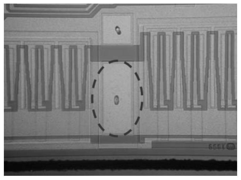
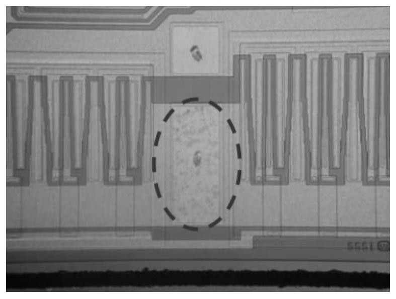
[0052] The effect detection of the following embodiments all adopts the following method: cut a 12-inch wafer with a Disco6362 wafer cutting machine, and the dilution factor of the cutting fluid is 3000 times, and observe with a metallographic microscope whether there are particles remaining on the surface of the wafer after cutting; in addition, the cutting Afterwards, the wafer was placed in the air, and the surface corrosion conditions were observed at 8 hours, 12 hours, 24 hours, and 36 hours, respectively.

[0053] The particle residual result of table 4 embodiment and comparative example 1

[0054]

[0055]

[0056] Among them: the minimum detection limit of ICP is 0.2ppm, and the result below the detection limit is recorded as N.D.; NG means: unqualified; OK: qualified.

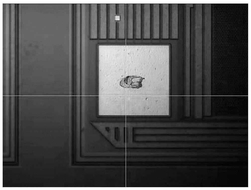
[0057] Comparison of whether there are particles left after cutting figure 1 with figure 2 as shown, figure ...


PUM


Abstract

The invention discloses wafer cutting fluid, belonging to the field of surface precision machining of photoelectronic devices. An oligomeric soap compound in the cutting fluid is ionized in a solution to form a negative charge group, and also has an amphiphilic structure similar to a surfactant, so the oligomeric soap compound can form a directionally arranged adsorption layer on the surface of a wafer, the negative charge group faces outwards and form a repulsive force with silicon chips having negative charges; and therefore, direct contact between the silicon chips and the surface of the wafer is prevented, and pollution of the silicon chips to the wafer is avoided. Meanwhile, a natural plant extract adopted in the cutting fluid is a compound with a heterocyclic structure having one or more N atoms or S atoms, electrons on a metal surface can be bonded more easily through the N or S atoms in the heterocyclic structure, so a protective film is formed, and electrochemical corrosion of a bonding pad on the surface of the semiconductor wafer is inhibited.

Description

technical field [0001] The invention relates to a wafer cutting fluid, which belongs to the field of surface precision processing of optoelectronic devices. Background technique [0002] In the semiconductor chip manufacturing process, the cutting process of the semiconductor wafer refers to a process in which the neatly distributed chips on the semiconductor wafer are separated by cutting the area called the dicing line after the semiconductor chip circuit manufacturing process is completed. . Observing under a 30x microscope, it can be found that the wafer semiconductor is composed of a collection of many independent units. These independent units are arranged neatly in rows or columns, and there is a "groove"-shaped strip between each row or column. These "grooves" are called cutting lines. After the cutting process is completed, individual tiny chips can be obtained. [0003] Usually thousands of chips are integrated on a semiconductor wafer, which is divided into ind...

Claims


Application Information

Patent Timeline
Patent Type & Authority Applications(China)
IPC IPC(8): C10M173/02C10N30/12C10N30/16
CPCC10M173/02C10M2207/289C10M2207/288C10M2209/08C10M2207/283C10M2215/221C10M2209/104C10M2209/108C10M2219/044C10M2209/084C10M2209/086C10M2205/04C10M2217/028C10M2205/022C10M2209/12C10M2217/024C10M2219/042C10M2215/04C10M2215/08C10M2215/28C10M2207/046C10M2207/022C10M2215/042C10M2201/062C10M2201/18C10M2219/104C10M2201/02
Inventor 侯军褚雨露
Owner 江苏奥首材料科技有限公司
Learn More