
Pressing and cutting head for transfer film

A transfer film and cutting head technology, which is applied in metal processing and other directions, can solve problems such as troublesome transfer film sticking to the cutter, and achieve the effect of reducing the defect rate and enhancing stability

Pending Publication Date: 2021-04-27
海盐三湾塑业有限公司
View PDF0 Cites 0 Cited by
  • Summary
  • Abstract
  • Description
  • Claims
  • Application Information

AI Technical Summary

Problems solved by technology

During the cutting process, the cut transfer film is easily coated on the cutter due to static electricity, which needs to be removed separately, which is troublesome

Method used


Image

  • Pressing and cutting head for transfer film
  • Pressing and cutting head for transfer film
  • Pressing and cutting head for transfer film

Examples


Embodiment Construction

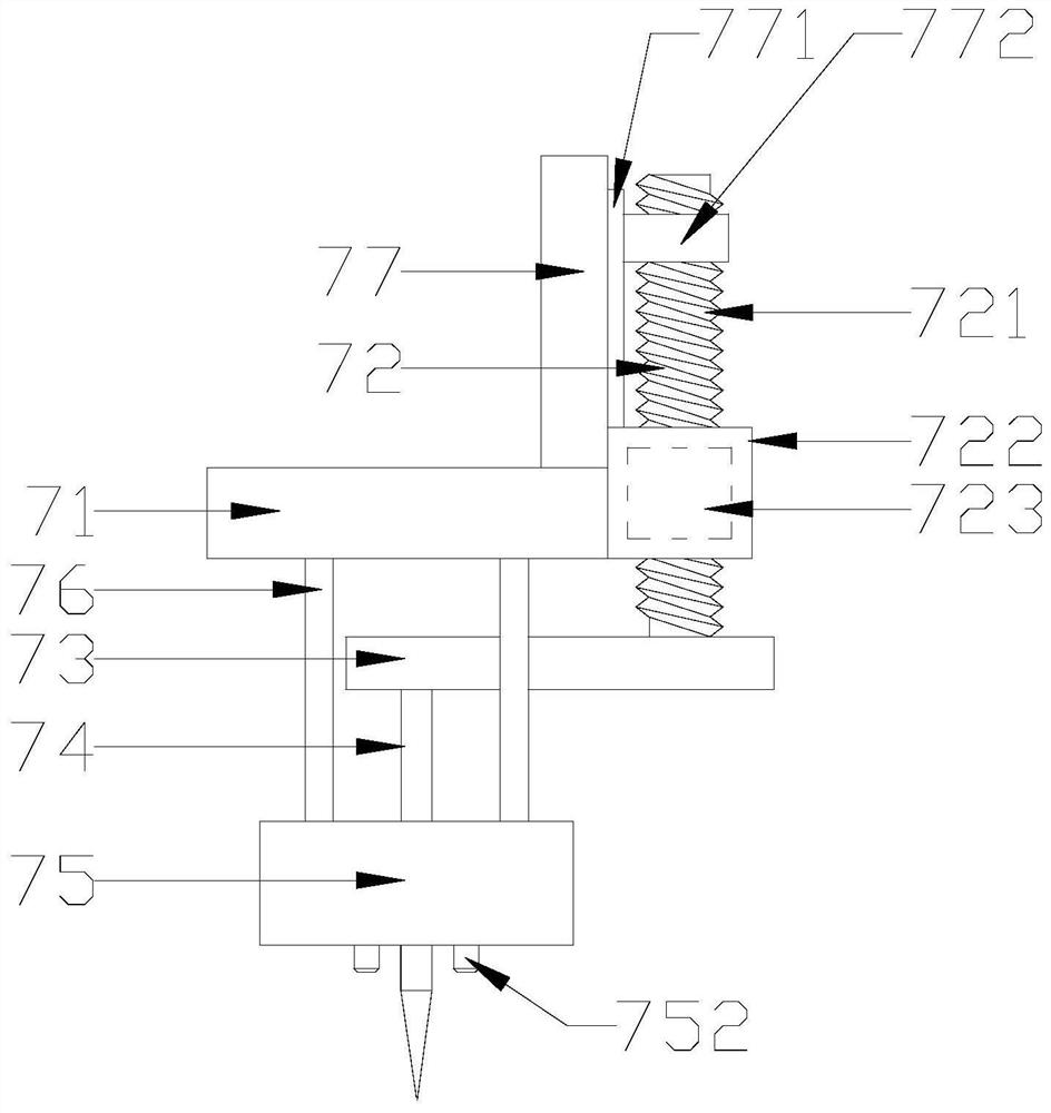
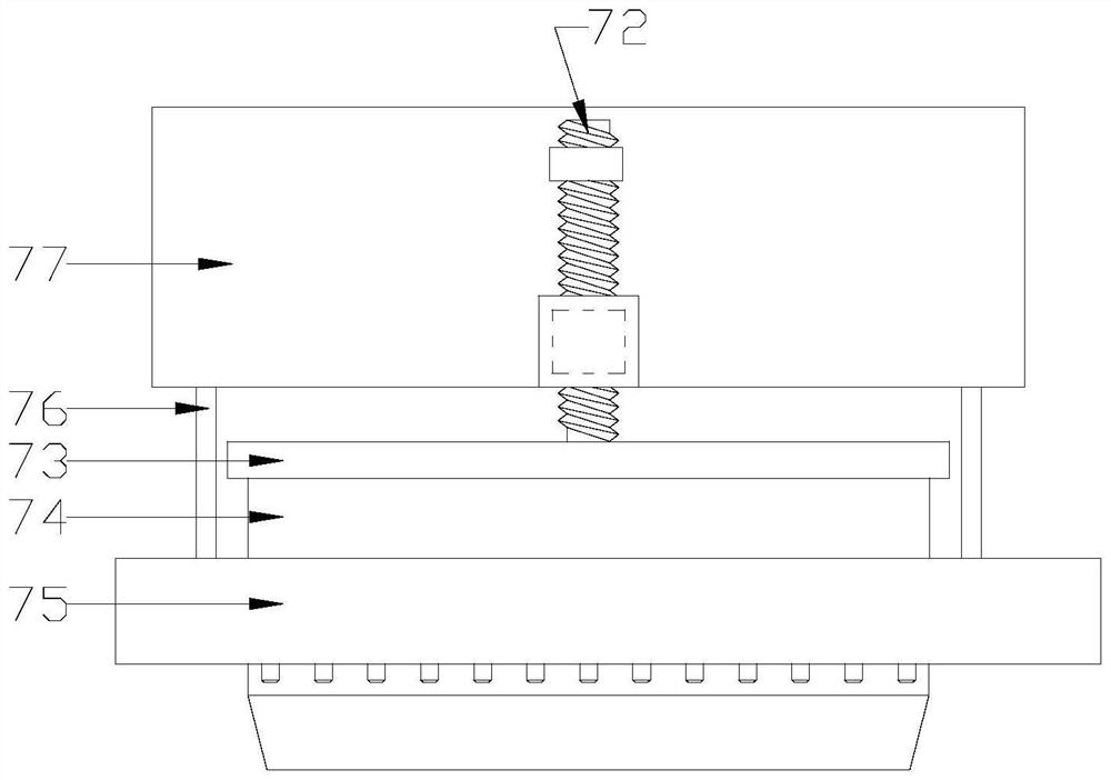
[0018] see Figure 1 to Figure 4 , a press cutting head for a transfer film of the present invention includes a cutter head top plate 71, a cutter head driver 72, a cutter head bottom plate 73, a blade 74, a partition box 75 and a support rod 76, and the two ends of several said support rods 76 They are respectively connected with the cutter head top plate 71 and the partition box 75. The cutter head bottom plate 73 is located between the cutter head top plate 71 and the partition box 75 and is driven up and down by the cutter head driver 72. The top of the blade 74 is connected to the cutter head bottom plate. 73 are connected to each other and the bottom end is arranged through the partition box 75. The bottom surface of the partition box 75 and located on the left and right sides of the blade 74 are respectively provided with several bumps 752. The blade driver 72 includes a blade screw 721, A cutter head motor 722 and a cutter head screw nut 723, the cutter head motor 722 ...


PUM


Abstract

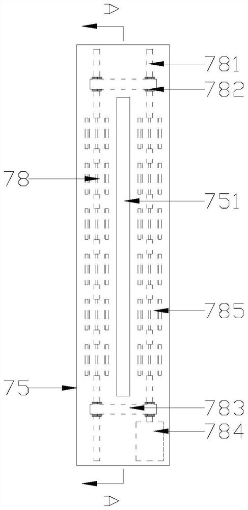
The invention discloses a pressing and cutting head for a transfer film. The pressing and cutting head comprises a tool bit top plate, a tool bit driver, a tool bit bottom plate, a blade, a partition box and supporting rods; the two ends of each of the multiple supporting rods are connected with the tool bit top plate and the partition box correspondingly, and the tool bit bottom plate is located between the tool bit top plate and the partition box and driven by the tool bit driver to move up and down; the top end of the blade is connected with the tool bit bottom plate, the bottom end of the blade penetrates out of the partition box, a plurality of protruding blocks are arranged at the positions, located at the left side and the right side of the blade, on the bottom face of the partition box respectively, and the tool bit bottom plate is driven by the tool bit driver to move up and down between the tool bit top plate and the partition box, so that the blade is driven to penetrate through the partition box to move up and down along a cutting groove, and when the blade retracts along the cutting groove after each time of cutting, the transfer film is directly blocked outside the bottom face of the partition box to be separated from the blade; and an air blowing assembly is arranged in the partition box, intermittent air blowing is achieved through a wind wheel which rotates intermittently, and the transfer film can be effectively sprayed open.

Description

【Technical field】 [0001] The present invention relates to the technical field of transfer films, in particular to the technical field of a press cutting head for transfer films. 【Background technique】 [0002] Aluminum gussets are based on aluminum alloy sheets, which are obtained by cutting, cutting and molding. There are two main types, one is home improvement integrated aluminum gussets, and the other is engineering aluminum gussets. With the development, the integrated aluminum gussets for home improvement have been varied, and various processing techniques have been applied to them. gusset. Thermal transfer printing is a process in which the decorative pattern on the thermal transfer printing is transferred to the surface of the decorated building material by one-time heating of the thermal transfer film to form a high-quality decorative film. The thermal transfer film is made of polyethylene film as the backing paper, with a decorative layer printed on it, and the su...

Claims


Application Information

Patent Timeline
Patent Type & Authority Applications(China)
IPC IPC(8): B26D1/08B26D7/18
CPCB26D1/085B26D7/1818B26D7/1854
Inventor 黄金明
Owner 海盐三湾塑业有限公司
Learn More