Slotless direct-current hybrid magnetic bearing

A hybrid magnetic bearing and winding technology, used in magnetic bearings, bearings, shafts and bearings, etc., can solve the problems of long axial length, large radial magnetic pole area, and occupying radial space.

Pending Publication Date: 2021-04-23
HUAIYIN INSTITUTE OF TECHNOLOGY
View PDF0 Cites 0 Cited by
  • Summary
  • Abstract
  • Description
  • Claims
  • Application Information

AI Technical Summary

Problems solved by technology

[0003] The common feature of the existing hybrid magnetic bearing structure is that the stator teeth are distributed along the circumference of the stator, and the windings are wound on the stator teeth. The design of the windings of this structure involves the number of turns, the cross-sectional area of ​​the wire, the current density, etc. In the radial space, the radial magnetic pole area cannot be maximized, the radial bearing capacity is small, the axial length is long, and the critical speed is low
In addition, the air-gap magnetic density of this structure is limited by the saturation of the teeth, and cannot be increased as required

Method used


Image

  • Slotless direct-current hybrid magnetic bearing
  • Slotless direct-current hybrid magnetic bearing
  • Slotless direct-current hybrid magnetic bearing

Examples


Embodiment approach 1

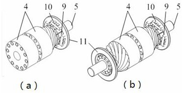
[0024] Specific implementation methods such as Figure 1-6As shown, the present invention discloses a slotless DC hybrid magnetic bearing, which includes a stator and a rotor. The stator includes a left stator core 1 , a right stator core 2 and a permanent magnet ring 3 . The two stator cores are disc ring structures; the permanent magnet ring 3 is axially magnetized, and the outer diameter of the permanent magnet ring 3 is the same as that of the two stator cores, and the two stator cores are the left stator core 1 and the left stator core respectively. The right stator core 2, the left stator core 1 and the right stator core 2 are connected through the permanent magnet ring 3. The rotor includes a rotor core 4 and a rotating shaft 5. The rotor core 4 is a ring structure, and the rotating shaft 5 runs through the rotor core 4. The rotor core 4 has an "H"-shaped structure along the radial section. The left and right sides of the rotor core 4 are respectively connected to the l...

Embodiment approach 2

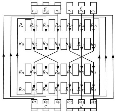
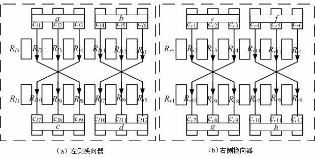
[0034] The difference between this embodiment and Embodiment 1 is that both sides of the rotor core 4 are connected to commutators, that is, when there are two commutators, the winding R l1 -R l12 , R r1 -R r12 For suspension control, the winding relative to the 4 circular inner slots of the rotor core: Winding R l1 with R l7 , Winding R l2 with R l8 , Winding R l3 with R l9 , Winding R l4 with R l10 , Winding R l5 with R l11 , Winding R l6 with R l12 , Winding R r1 with R r7 , Winding R r2 with R r8 , Winding R r3 with R r9 , Winding R r4 with R r10 , Winding R r5 with R r11 , Winding R r6 with R r12 In series in the same direction, one end of the 12 windings on the left is connected to the 12 commutator segments 9 in the left commutator, one end of the 12 windings on the right is connected to the 12 commutator segments 9 in the right commutator, each 3 Each commutator segment 9 corresponds to one carbon brush 10 , and each commutator is provided with...


PUM


Abstract

The invention discloses a slotless direct-current hybrid magnetic bearing. The slotless direct-current hybrid magnetic bearing comprises a stator and a rotor, and the stator comprises a left stator iron core, a right stator iron core and a permanent magnet ring. The permanent magnet ring is axially magnetized, the outer diameter of the permanent magnet ring is the same as that of the stator iron cores, and the left stator iron core is connected with the right stator iron core through the permanent magnet ring. The rotor comprises a rotor iron core and a rotating shaft. 4N circular inner grooves penetrate through the rotor iron core along the circumferential edge, one ends of two windings opposite to each other along the circumference are in short joint, and the other ends of the two windings are connected with commutator segments. The commutator segments are connected with a bipolar switch power amplifier through carbon brushes, and the rotor iron core and the stator iron cores are opposite in position to form an air gap. Static bias magnetic flux is provided by the permanent magnet ring, and corresponding bias magnetic flux is adjusted by a control magnetic flux generated by electrifying the inner groove windings in the rotor. The hybrid magnetic bearing windings of the structure are embedded in the rotor grooves, the effective area between the stator and the rotor is increased, the suspension force density is increased, and the hybrid magnetic bearing has the advantages of being compact in structure, good in stability and high in utilization rate.

Description

technical field [0001] The invention relates to a non-mechanical contact magnetic bearing, in particular to a slotless DC hybrid magnetic bearing, which can be used as a non-contact suspension support for high-speed transmission components such as a flywheel system, a machine tool electric spindle, and a centrifuge. Background technique [0002] The magnetic bearing is a new type of high-performance bearing that uses the electromagnetic force between the stator and the rotor to suspend the rotor in space, so that there is no mechanical contact between the stator and the rotor. At present, magnetic bearings are divided into the following three types according to the way the magnetic force is provided: (1) Active magnetic bearings, the bias magnetic field is generated by the bias current, and the control flux generated by the control current and the bias flux are superimposed on each other, thereby generating a controllable The levitation force of this kind of magnetic bearing...

Claims


Application Information

Patent Timeline
IPC IPC(8): F16C32/04
CPCF16C32/044F16C32/0461F16C32/0468F16C32/047
Inventor 王紫欣张涛
Owner HUAIYIN INSTITUTE OF TECHNOLOGY
Why Eureka
Try Eureka