Bar and pipe polishing and grinding device for machining
A technology for polishing and grinding pipes, which is applied in the direction of grinding drive devices, metal processing equipment, grinding/polishing equipment, etc. It can solve problems such as low work efficiency, uneven grinding and polishing, and increased workload for workers to achieve clamping stability. Effect
- Summary
- Abstract
- Description
- Claims
- Application Information
AI Technical Summary
Problems solved by technology
Method used
Image
Examples
specific Embodiment approach 1
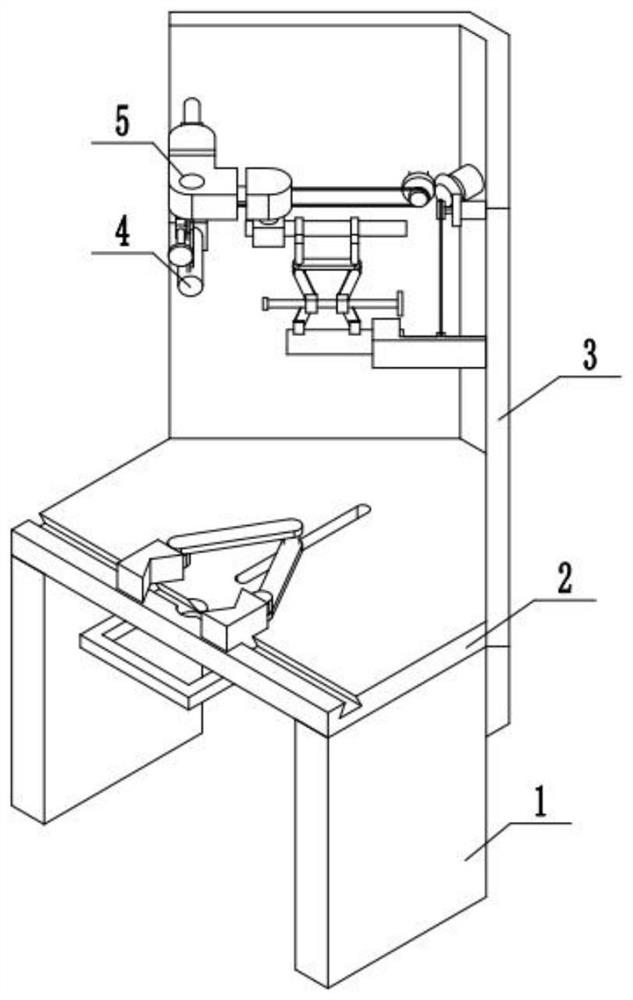
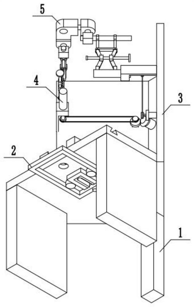
[0034] Combine below figure 1 , 2 Illustrating this embodiment, a polishing and grinding device for rods and pipes for processing includes a fixed support base 1, a rod and pipe fixing device 2, a V-shaped baffle 3, a grinding driving device 4 and a grinding device 5. The fixed support base 1 is fixedly installed under the bar and pipe fixing device 2, the bar and pipe fixing device 2 is fixedly installed with a V-shaped baffle 3, the grinding driving device 4 is installed on the V-shaped baffle 3, and the grinding driving device 4 is installed with a grinding device 5.
specific Embodiment approach 2
[0036] Combine below image 3 , 4 , 5, 6, and 7 describe this embodiment, and this embodiment further describes Embodiment 1. The rod and pipe fixing device 2 includes a fixing base plate 201 and a fixing device body 202. The fixing base plate 201 is installed with a fixing device body 202. ;
[0037] The fixed bottom plate 201 includes a sliding groove 203, a trapezoidal groove 204, and a fixed bottom plate body 205. The fixed bottom plate body 205 is provided with a sliding groove 203, and the fixed bottom plate body 205 is provided with a trapezoidal groove 204;
[0038]The fixing device body 202 includes a transmission slide bar 206, a transmission rack A207, a transmission gear A208, a transmission rack B209, a rack limit block 210, a connecting rod 211, a clamping block 212, a trapezoidal slider 213, and a transmission slider. 206 is slidably installed in the sliding groove 203 provided on the fixed base plate body 205, the transmission sliding rod 206 is fixedly insta...
specific Embodiment approach 3
[0040] Combine below Figure 8 , 9 , 10, 11, and 12 illustrate this embodiment, and this embodiment further describes Embodiment 1. The grinding driving device 4 includes a power mechanism 401 and a driving mechanism 402, and a driving mechanism 402 is installed on the power mechanism 401;
[0041] The power mechanism 401 includes a power motor 403, a drive bevel gear 404, a drive spur gear 405, a gear fixed shaft 406, a drive pulley A407, a drive belt 408, a drive pulley B409, a pulley fixed shaft 410, a fixed frame body 411, and a power motor. 403 is fixedly installed on the V-shaped baffle 3, the output end of the power motor 403 is installed with a transmission bevel gear 404, the transmission bevel gear 404 and the driving spur gear 405 are meshed with the teeth, and the driving spur gear 405 is fixedly installed on the gear fixed shaft 406 , the gear fixed shaft 406 is movably installed on the V-shaped baffle 3, the transmission bevel gear 404 is fixedly installed with ...
PUM
 Abstract
Description
Claims
Application Information
 - R&D
- Intellectual Property
- Life Sciences
- Materials
- Tech Scout
- Unparalleled Data Quality
- Higher Quality Content
- 60% Fewer Hallucinations
Browse by: Latest US Patents, China's latest patents, Technical Efficacy Thesaurus, Application Domain, Technology Topic, Popular Technical Reports.
© 2025 PatSnap. All rights reserved.Legal|Privacy policy|Modern Slavery Act Transparency Statement|Sitemap|About US| Contact US: help@patsnap.com


