Waste heat recovery system for thermal power plant
A technology of waste heat recovery system and thermal power plant, which is applied in the direction of steam application, steam engine device, machine/engine, etc. It can solve the problems of heat loss and low efficiency of waste heat recovery, so as to improve heat recovery, improve recovery efficiency and reduce harmful substances Effect
- Summary
- Abstract
- Description
- Claims
- Application Information
AI Technical Summary
Problems solved by technology
Method used
Image
Examples
Embodiment 1
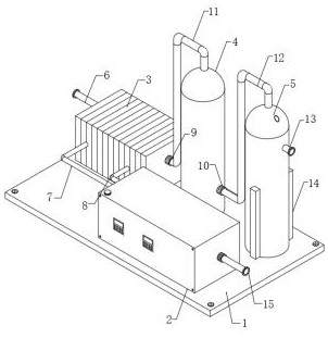
[0030]The dust removal mechanism includes a plurality of mounting seats 20 and a plurality of electrostatic rods 21. The bottom of the inner wall of the flue gas treatment equipment A4 is equidistantly fixed with a plurality of mounting seats 20, and one side of the plurality of mounting seats 20 is fixedly installed with electrostatic rods. Rod 21, the bottom end of the flue gas treatment equipment A4 is equipped with an ash hopper 22, and the inside of the ash hopper 22 is fixed with a solenoid valve. The charge on the object in the ion radiation area is neutralized. When the object's surface is negatively charged, it will attract the positive charge in the radiation area. When the object's surface is positively charged, it will attract radiation. The negative charge in the area can effectively remove the dust in the flue gas.
Embodiment 2
[0032] The reaction mechanism 14 includes two equipment boxes 24, a plurality of stirring shafts 25, a plurality of connecting shafts 26, a plurality of gears 28, a chain 27 and a driving motor 29, and the bottoms on both sides of the inner wall of the flue gas treatment equipment B5 are rotationally connected with a plurality of stirring shafts 25. One end of a plurality of stirring shafts 25 passes through the flue gas treatment equipment B5 and is fixedly connected with a connecting shaft 26. The surfaces of the plurality of connecting shafts 26 are sleeved and connected with gears 28, and the plurality of gears 28 are connected through a chain 27. , the bottoms on both sides of the flue gas treatment equipment B5 are fixedly equipped with equipment boxes 24, and the insides of the two equipment boxes 24 are fixedly installed with driving motors 29, and the output shafts of the two driving motors 29 are respectively connected to the corresponding connecting shaft 26 ends fix...
Embodiment 3
[0034] The water circulation equipment 2 includes an outer box body 30, an inner box body 31 and thermal insulation cotton 32. The inner box body 31 is sheathed and connected to the outer box body 30, and the outer box body 30 and the inner box body 31 are filled with thermal insulation cotton 32. The thermal insulation cotton 32 filled has a better thermal insulation effect and reduces the loss of heat. The side of the fixed plate 1 is fixedly equipped with a PLC controller, the first air pump 9, the second air pump 10, the driving motor 29, and the circulating pump 33. and the output pump 34 are electrically connected to the external power supply through the PLC controller, and the inner wall of the water circulation equipment 2 is respectively equipped with a liquid level sensor and a temperature sensor, and the installed liquid level sensor and the temperature sensor are convenient for observing the liquid level and the inside of the water circulation equipment 2. The tempe...
PUM
 Abstract
Description
Claims
Application Information
 - R&D Engineer
- R&D Manager
- IP Professional
- Industry Leading Data Capabilities
- Powerful AI technology
- Patent DNA Extraction
Browse by: Latest US Patents, China's latest patents, Technical Efficacy Thesaurus, Application Domain, Technology Topic, Popular Technical Reports.
© 2024 PatSnap. All rights reserved.Legal|Privacy policy|Modern Slavery Act Transparency Statement|Sitemap|About US| Contact US: help@patsnap.com


