a cooling device
A technology of heat dissipation device and fins, applied in cooling/ventilation/heating transformation, electrical components, electrical equipment structural parts, etc., can solve the problem that air cooling, liquid cooling and other technologies cannot meet the heat dissipation requirements, and achieve good heat dissipation effect. , convenient maintenance and cleaning, increase the effect of disturbance
- Summary
- Abstract
- Description
- Claims
- Application Information
AI Technical Summary
Problems solved by technology
Method used
Image

Examples
Embodiment 1
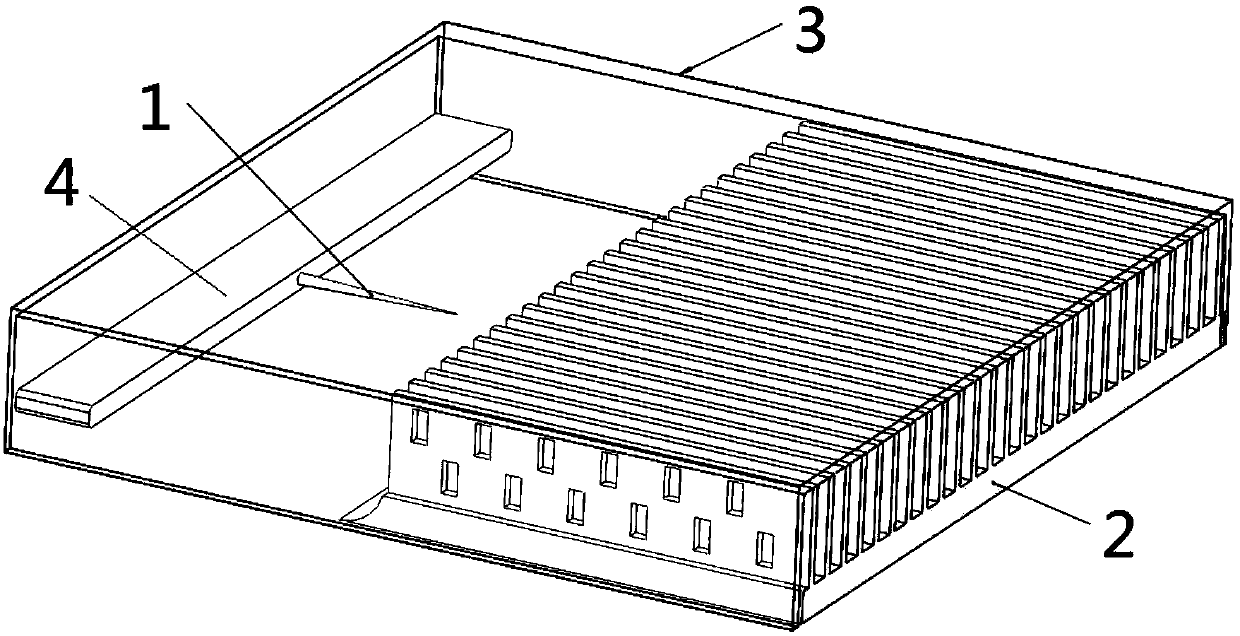
[0029] The present invention provides a heat dissipation device. Embodiment 1 is as follows: it includes a primary emitter electrode 1 , a fin body 2 and a casing 3 . In the technical solution provided by the present invention, the fin body 2 is connected to one side inside the housing, and the connection method can be a fixed connection or a movable connection; the discharge end of the first-stage emitter electrode 1 is arranged on the other side of the inside of the housing facing the fin body 2 The non-discharge end of the first-level emitter electrode 1 is connected to the bottom of the heat sink, and the connection method can be a fixed connection; the distance between the discharge end of the first-level emitter electrode 1 and the fin body 2 is 5mm-15mm; the first-level emitter electrode The discharge end of 1 is connected to the fin body 2 with a DC power supply of 4kV-10kV.
[0030] further, figure 1 Example 2 obtained through modification of Example 1.
Embodiment 2
[0031] Embodiment 2 provides a heat dissipation device, which includes a primary emitter electrode 1 , a fin body 2 , a casing 3 and a slidable fixing frame 4 . see figure 1 , in the technical solution provided by the present invention, the fin body 2 is connected to one side inside the shell, and the connection method can be a fixed connection or a movable connection; the discharge end of the primary emitter electrode 1 is located on the other side of the shell inside the Side; the non-discharge end of the primary emitter electrode 1 is connected to the slidable fixing frame 4, and the connection method can be fixed connection or movable connection; the distance between the discharge end of the primary emitter electrode 1 and the fin body 2 is 5mm-15mm; The discharge end of the primary emitter electrode 1 and the fin body 2 are connected with a DC power supply of 4kV-10kV. The slidable fixing frame 4 is arranged inside the casing 3 through the inner surface of the casing 3 a...
Embodiment 3
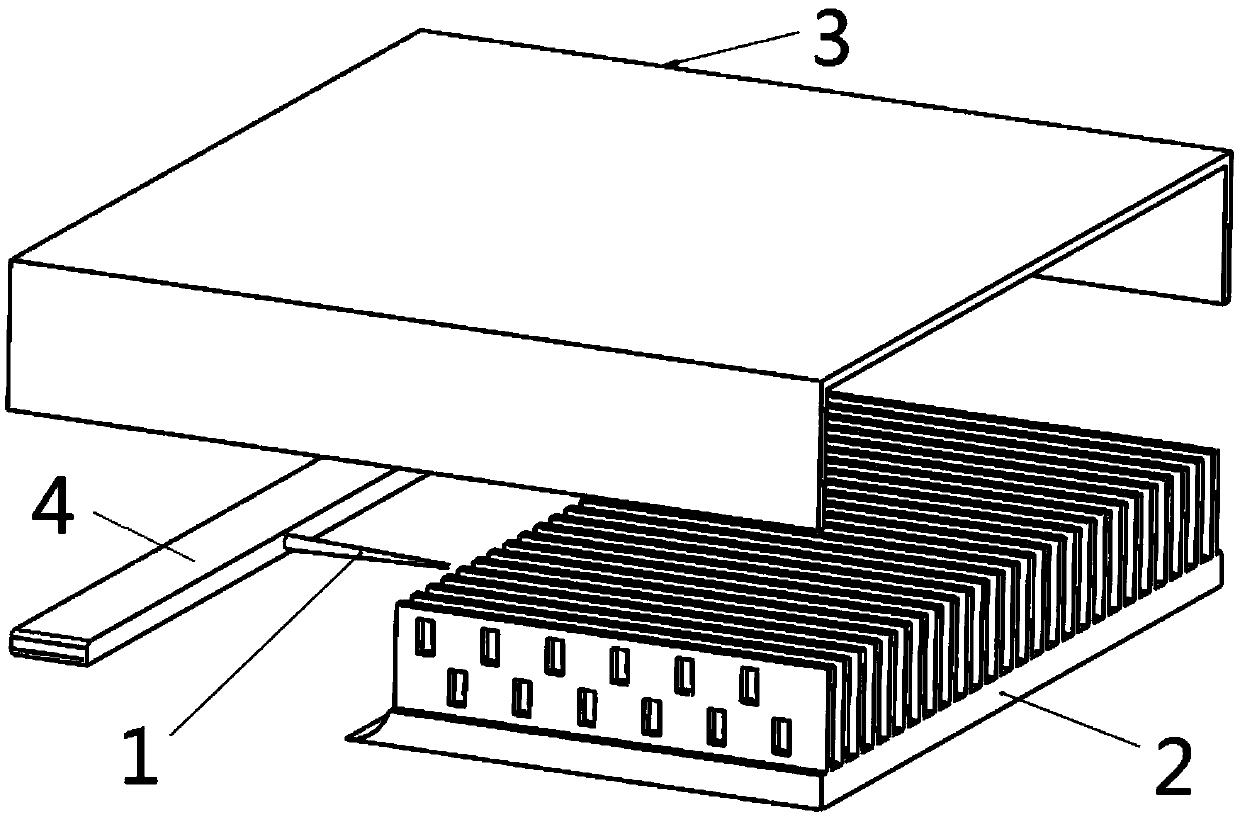
[0033] Embodiment 3 provides a heat dissipation device, which includes a primary emitter electrode 1 , a fin body 2 , a casing 3 and a slidable fixing frame 4 . see figure 2 , in the technical solution provided by the present invention, the fin body 2 is connected to one side inside the shell, and the connection method can be a fixed connection or a movable connection; the discharge end of the primary emitter electrode 1 is located on the other side of the shell inside the Side; the non-discharge end of the primary emitter electrode 1 is connected to the slidable fixing frame 4, and the connection method can be fixed connection or movable connection; the distance between the discharge end of the primary emitter electrode 1 and the fin body 2 is 5mm-15mm; The discharge end of the primary emitter electrode 1 and the fin body 2 are connected with a 4kV-10kV DC power supply; the material of the shell 3 is epoxy resin or glass fiber, the thickness is 1mm, the width of the shell is...
PUM
 Abstract
Description
Claims
Application Information
 - Generate Ideas
- Intellectual Property
- Life Sciences
- Materials
- Tech Scout
- Unparalleled Data Quality
- Higher Quality Content
- 60% Fewer Hallucinations
Browse by: Latest US Patents, China's latest patents, Technical Efficacy Thesaurus, Application Domain, Technology Topic, Popular Technical Reports.
© 2025 PatSnap. All rights reserved.Legal|Privacy policy|Modern Slavery Act Transparency Statement|Sitemap|About US| Contact US: help@patsnap.com