An anti-condensation non-assisted ventilation device for ring network cabinets
A ventilation device and anti-condensation technology, which is applied in the substation/distribution device enclosure, substation/switchgear cooling/ventilation, substation/switch layout details, etc. Easy to install, lower temperature effect
- Summary
- Abstract
- Description
- Claims
- Application Information
AI Technical Summary
Problems solved by technology
Method used
Image
Examples
Embodiment 1
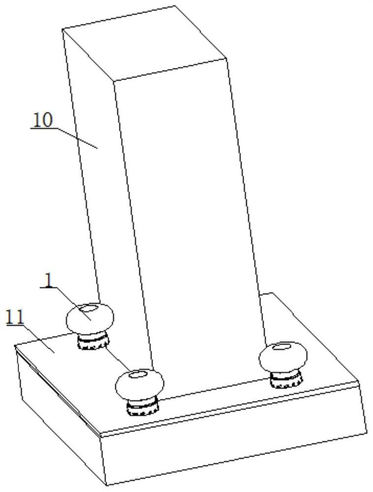
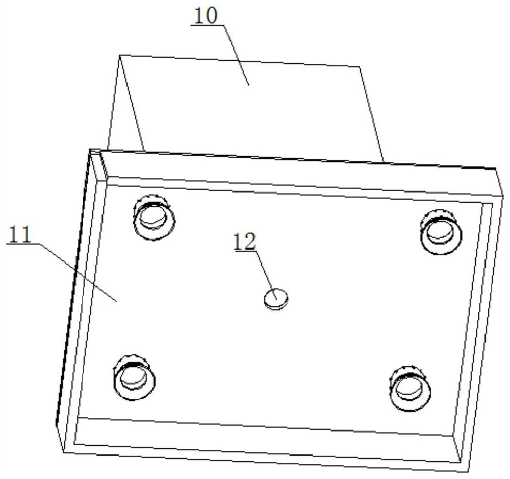
[0035] An anti-condensation non-assisted ventilation device for a ring network cabinet, such as figure 1 with figure 2 As shown, it includes a support base 11 located above the cable trench and a cabinet body 10 located above the support base 11. The cabinet body 10 and the support base 11 are connected by bolts. The support base 11 is a shell structure with an open lower end surface, supporting The upper end surface of the seat 11 is provided with four ventilation devices, and the four ventilation devices are respectively arranged at the corners of the cabinet body 10. The upper end surface of the support seat 11 is provided with four through holes and a threading hole 12, and the threading hole 12 is connected with the cabinet body. cable fit in the body 10;
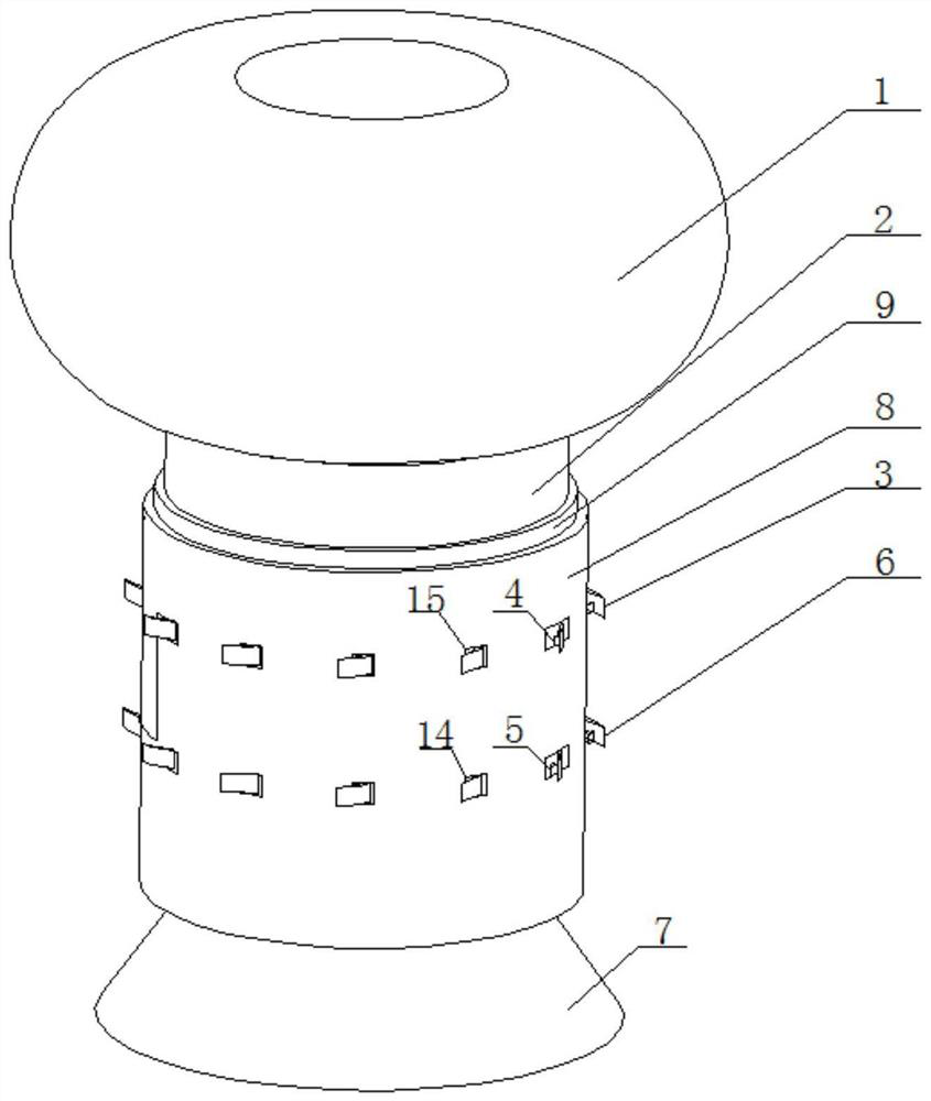
[0036] Such as Figure 3-6As shown, the ventilation device includes a wind cap 1, a connecting pipe 2 and a support tube 8; specifically: the wind cap 1 adopts a non-powered wind cap; The upper end surface of 8 and...
Embodiment 2
[0040] This embodiment 2 is the same as embodiment 1, the difference is that, as Figure 3-6 As shown, the present embodiment 2 is provided with an extension tube 17 in the connecting tube 2, specifically: the extension tube 17 is a transparent tube, the axis of the extension tube 17 coincides with the axis of the connecting tube 2, and the extension tube 17 and the connecting tube 2 Thread fit, the upper end of the extension pipe 17 is welded and fixed with the hood 1. By twisting the extension tube 17, the extension tube 17 is unscrewed out of the connecting tube 2, so that the total length of the connecting tube 2 and the extension tube 17 is increased, thereby extending the flow path of the air.
[0041] Further, the lower end of the connecting pipe 2 is provided with a diversion pipe 7, the inner cavity of the diversion pipe 7 is a gradually expanding structure from top to bottom, and the upper end of the diversion pipe 7 is connected with the connecting pipe 2, specifica...
PUM
 Abstract
Description
Claims
Application Information
 - R&D
- Intellectual Property
- Life Sciences
- Materials
- Tech Scout
- Unparalleled Data Quality
- Higher Quality Content
- 60% Fewer Hallucinations
Browse by: Latest US Patents, China's latest patents, Technical Efficacy Thesaurus, Application Domain, Technology Topic, Popular Technical Reports.
© 2025 PatSnap. All rights reserved.Legal|Privacy policy|Modern Slavery Act Transparency Statement|Sitemap|About US| Contact US: help@patsnap.com


