
Material suction device for chemical raw material inspection

A material suction device and chemical raw material technology, which is applied in the direction of sampling device, transportation and packaging, and conveying bulk materials, etc., can solve the problems of low randomness of extraction, deviation, and slow manual sampling speed, and achieve the effect of improving accuracy

Inactive Publication Date: 2021-04-09
徐丽侠
View PDF0 Cites 0 Cited by
  • Summary
  • Abstract
  • Description
  • Claims
  • Application Information

AI Technical Summary

Problems solved by technology

The speed of manual sampling is slow, the randomness of sampling is low, the sampling position of the sampler is relatively single, and the sampling inspection results may have a large deviation from the real results

Method used


Image

  • Material suction device for chemical raw material inspection
  • Material suction device for chemical raw material inspection
  • Material suction device for chemical raw material inspection

Examples


Embodiment 1

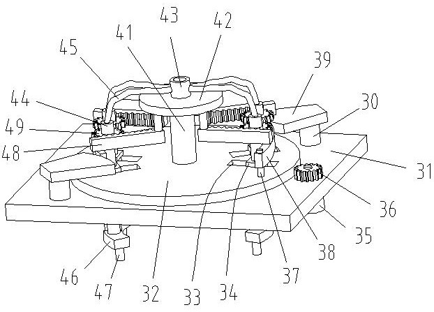
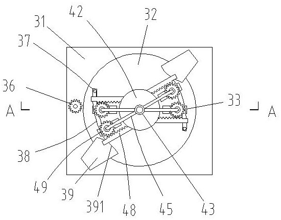
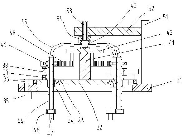
[0039] The invention discloses a suction device for testing chemical raw materials. The suction device 3 includes:

[0040] a plate 31;

[0041] A turntable 32, two groups of slide grooves 33 are arranged symmetrically on the turntable 32, and the turntable 32 is rotatably connected in the central hole of the flat plate 31;

[0042] A rotating device, the rotating device is used to control the rotation of the turntable 32 in the central hole of the flat plate 31;

[0043] Two groups of sliders 34, each group of sliders 34 are 2, the sliders 34 are arranged in the chute 33 one by one and can slide back and forth along the chute 33, the slider 34 is provided with vertical mounting holes;

[0044] Two groups of bronchus 44, the bronchus 44 is correspondingly fixed in the installation hole on the slider 34, and can rotate in the installation hole;

[0045] A support disc 42, the support disc 42 is coaxially fixed on the upper center of the turntable 32 through the support column...

Embodiment 2

[0054] On the basis of Embodiment 1, the rotating device includes:

[0055] A second motor 35, the second motor 35 is fixed on one side of the flat plate 31;

[0056] A gear one 36, the gear one 36 is fixed on the main shaft of the motor two 35;

[0057] A gear ring, the gear ring is sleeved on the outer side of the turntable 32 and meshed with the first gear 36 .

[0058] Of course, the rotating device can adopt other rotating structures in the prior art.

Embodiment 3

[0060] On the basis of Embodiment 1, the lower end of each bronchus 44 is connected to the transition box 46, and the bottom of the transition box 46 is connected to a group of suction nozzles 47;

[0061] The outer side of each bronchus 44 is sleeved with a fixed gear 2 49 , and the lower side of the support disc 42 is fixedly connected with a rack 48 , and the rack 48 is meshed with the second gear 49 .

[0062] When the power unit control slider 34 reciprocally slides in the chute 33, the bronchus 44 is driven to rotate under the meshing effect of the rack 48 and the second gear 49, thereby driving the transition box 46 to rotate, which can increase the movement of the suction nozzle 47 range, thereby further improving the sampling effect. Due to the arc-shaped structure of the arc-shaped plate, the displacements of the two sliders sliding to the center of the circle are different. The greater the rotation of the arc-shaped plate, the greater the displacement gap between th...


PUM


Abstract

The invention relates to a material suction device for chemical raw material inspection. The material suction device comprises a flat plate, a rotary disc, a rotating device, sliding blocks, branch air pipes, a supporting disc and a collecting barrel, two sets of sliding grooves are symmetrically formed in the rotary disc, and the rotary disc is rotationally connected into a center hole of the flat plate; the rotating device is used for controlling the rotary disc to rotate in the central hole of the flat plate; the sliding blocks are arranged in the sliding grooves in a one-to-one correspondence mode and can slide along the sliding grooves in a reciprocating mode; the two groups of branch air pipes are correspondingly fixed on the sliding blocks; the supporting disc is coaxially fixed to the center of the upper side of the rotary disc through a supporting column; and the collecting barrel. The material suction device has the beneficial effects that in the material suction process, the rotary disc is controlled by the rotating device to rotate in the center hole of the flat plate, so that the axial position of branch air pipe material suction can be continuously changed, the sliding blocks are controlled by a power device to slide back and forth in the sliding grooves, the radial position of branch air pipe material suction can be changed, sampling parts are denser, and the accuracy of sampling inspection is improved.

Description

technical field [0001] The invention relates to the technical field of chemical raw material inspection, in particular to a suction device for chemical raw material inspection. Background technique [0002] Parameters such as moisture content in chemical raw materials have an impact on subsequent processing. Generally, partial sampling is performed in the overall material, and the overall quality is determined by the inspection parameters of the sample. In the prior art, samples are usually taken manually or by a sampler. The speed of manual sampling is slow, the randomness of sampling is low, and the sampling position of the sampling device is relatively single, so the sampling inspection results may have a large deviation from the real results. Contents of the invention [0003] In order to make up for the deficiencies in the prior art, the invention proposes a suction device for chemical raw material inspection to solve the technical problems in the prior art. [0004...

Claims


Application Information

Patent Timeline
IPC IPC(8): B65G53/24B65G53/34B65G53/52B65G53/54G01N1/14
CPCB65G53/24B65G53/34B65G53/52B65G53/54G01N1/14
Inventor 不公告发明人
Owner 徐丽侠
Learn More