
Anti-overload torque sensor based on film sputtering

A torque sensor, anti-overload technology, applied in the direction of instruments, torque measurement, measuring devices, etc., can solve the problem of strain gauge life, stability, precision, low dynamic response and anti-vibration ability, narrow temperature range cannot meet the use requirements, Unable to meet the use requirements and other problems, to achieve the effect of good compactness, small internal stress and strong adhesion

Inactive Publication Date: 2021-04-06
SHAANXI ELECTRICAL APPLIANCE RES INST
View PDF7 Cites 4 Cited by
  • Summary
  • Abstract
  • Description
  • Claims
  • Application Information

AI Technical Summary

Problems solved by technology

[0003] However, most of the known torque sensors currently use the traditional strain gauge pasting method. The life, stability, accuracy, dynamic response and vibration resistance of traditional strain gauges are relatively low, and the temperature range of traditional strain gauges is -30°C-100°C. , the temperature range is narrower and cannot meet the requirements of use
[0004] At present, the overload requirement of the known torque sensor is mostly double overload. When the operating condition of the sensor is five times overload or even higher, the elastic beam of the sensor will reach the yield limit of the material itself, and damage will occur, resulting in sensor failure.
Therefore, the requirements for use cannot be met

Method used


Image

  • Anti-overload torque sensor based on film sputtering
  • Anti-overload torque sensor based on film sputtering
  • Anti-overload torque sensor based on film sputtering

Examples


Embodiment Construction

[0035] The present invention will be described in detail below with reference to the accompanying drawings and examples.

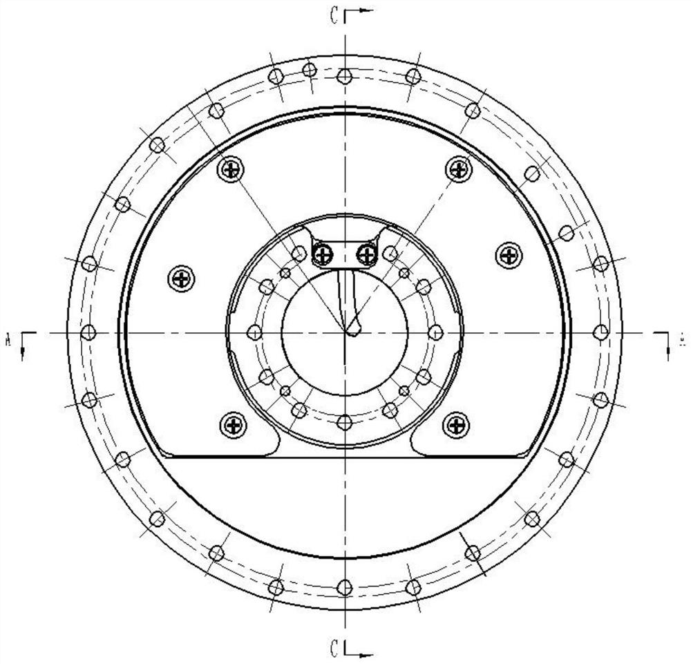
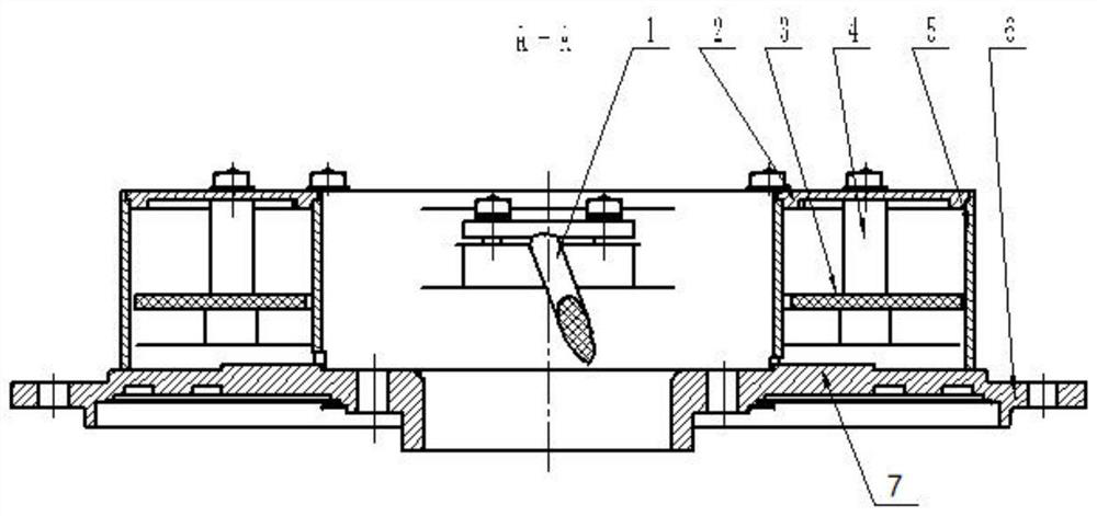
[0036] This embodiment provides a kind of anti-overload torque sensor based on thin film sputtering, see attached Figure 1-3 , including: output cable 1, upper cover plate 2, circuit board 3, pad column 4, housing 5, elastic body 6, strain beam 7 and film strain gauge 8;

[0037] The housing 5 is an annular housing, the upper end of the annular housing is open, and a connecting rod is installed at the lower end to connect the inner cylinder and the outer cylinder of the annular housing as a whole; in this embodiment, the housing 5 After being cut off by a plane parallel to its axis, the remaining C-shaped shell, the space formed by the cut off part is used for installing external components;

[0038] See attached Figure 4-5 , the elastic body 6 is an annular plate, and the annular plate is divided into three coaxial annular structures from the inside t...


PUM


Abstract

The invention discloses an anti-overload torque sensor based on film sputtering. The anti-overload torque sensor comprises an output cable, a circuit board, a cushion column, a shell, an elastic body, a strain beam and film strain gauges, wherein the elastic body is an annular plate, the annular plate is sequentially divided into an inner edge section, an installation ring section and an outer edge section from inside to outside, the installation ring section is provided with an integrally formed rectangular bulge serving as the strain beam, the shell is coaxially mounted on the installation ring section of the elastic body, the circuit board is located in the annular cavity of the shell and installed on the installation annular section of the elastic body through the cushion column, one end of the output cable is welded on the circuit board, the other end of the output cable is connected with an external electric connector, and the strain resistors of the two film strain gauges are sputtered on the strain beam of the elastic body through a sputter coating technology. According to the invention, a sensitive film is prepared by adopting a sputter coating process, and an anti-torque limiting structure is arranged, so that when a torque load exceeds a set threshold value, the anti-torque limiting structure can play a role in overload protection of the elastic beam.

Description

technical field [0001] The invention belongs to the technical field of electronic sensing weighing instruments, and in particular relates to an anti-overload torque sensor based on thin film sputtering. Background technique [0002] The purpose of the torque sensor is to measure the physical quantity of one-dimensional torque. Resistance strain sensor is the most widely used torque sensor at home and abroad. It adopts the traditional method of pasting strain gauges on the surface of elastic beams. When physical quantities such as torque act on the elastic beams, it will cause changes in the stress and strain of the components, which in turn will cause changes in the resistance of the strain gauges. The changes in resistance will be processed by the circuit. Signal output, this kind of sensor is widely used in the measurement of torque. [0003] However, most of the known torque sensors currently use the traditional strain gauge pasting method. The life, stability, accuracy...

Claims


Application Information

Patent Timeline
Patent Type & Authority Applications(China)
IPC IPC(8): G01L3/10
CPCG01L3/108
Inventor 姜鑫高波屈文轩潘婷蔺露
Owner SHAANXI ELECTRICAL APPLIANCE RES INST
Learn More