
Keel cutting and bending equipment and using method thereof

A keel and cutting technology, used in metal processing equipment, other manufacturing equipment/tools, feeding devices, etc., can solve the problems of insufficient lap strength, area size, large cutting error, etc., to ensure stability, fire prevention, etc. High-grade, long-life effect

Pending Publication Date: 2021-03-30
ZHEJIANG YASHA DECORATION
View PDF1 Cites 0 Cited by
  • Summary
  • Abstract
  • Description
  • Claims
  • Application Information

AI Technical Summary

Problems solved by technology

The existing two methods have the following problems: in the first method, the wooden blocks cannot meet the standard requirements for class A fire protection of the suspended ceiling; in the second method, after cutting and installing, there are large cutting errors, which may cause the installation flatness to fail to meet the requirements , and the size of the overlapping surface after cutting depends solely on the thickness of the glyph keel itself, the overlapping strength is insufficient, and there is a problem of poor stability of the ceiling plate
However, there is a lack of integrity between the keel and the adjusting plate. When the entire keel ceiling system is lapped and installed on the wall hanger, the main stress of the keel ceiling system will be concentrated at the connection position between the keel and the adjusting plate, and the strength requirements for the fixing parts are extremely high. high
Moreover, although the device does not limit the material selection of the adjusting plate, it can be expected that if the adjusting plate is made of hard material, if there is a problem of inconsistency in size when it is inserted into the keel later, the size adjustment of the adjusting plate will change. It is relatively difficult to obtain, and when the adjustment plate is made of relatively soft materials, the fire performance and bearing strength of this type of material must be considered, which cannot solve the above technical problems

Method used


Image

  • Keel cutting and bending equipment and using method thereof
  • Keel cutting and bending equipment and using method thereof
  • Keel cutting and bending equipment and using method thereof

Examples


Embodiment Construction

[0030] In order to make the purpose, technical solutions and advantages of the embodiments of the present invention clearer, the technical solutions in the embodiments of the present invention will be clearly and completely described below in conjunction with the drawings in the embodiments of the present invention. Obviously, the described embodiments It is a part of embodiments of the present invention, but not all embodiments. Based on the embodiments of the present invention, all other embodiments obtained by persons of ordinary skill in the art without making creative efforts belong to the protection scope of the present invention. It should be noted that, in the case of no conflict, the embodiments in the present application and the features in the embodiments can be combined arbitrarily with each other.

[0031]It should be noted that in this article, relational terms such as first and second are only used to distinguish one entity or operation from another entity or op...


PUM


Abstract

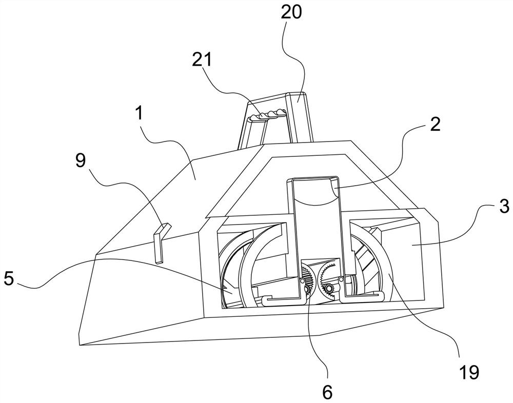
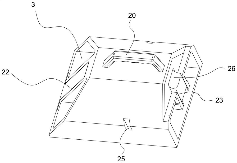
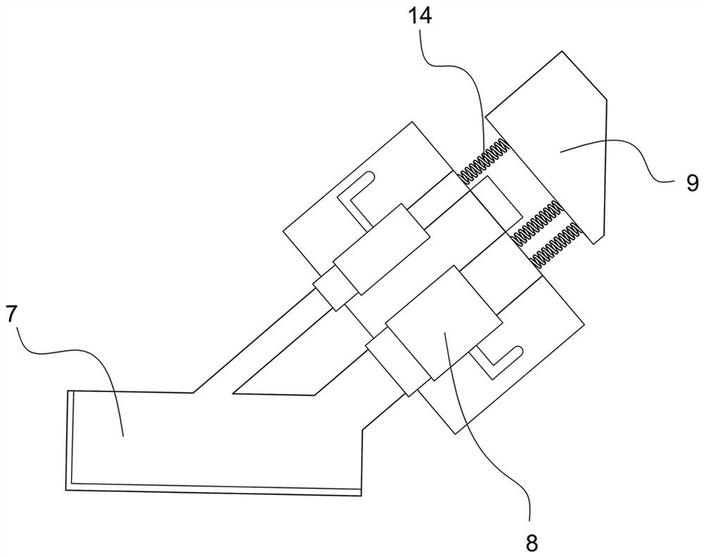
The invention discloses keel cutting and bending equipment, and relates to the technical field of keel machining. The keel cutting and bending equipment comprises a containing body, an inserting channel for allowing an n-shaped keel to be inserted is formed in the containing body, and containing cavities are further formed in the two sides of the inserting channel in the containing body; the keelcutting and bending equipment further comprises a cutting mechanism and a bending mechanism which are sequentially arranged in the containing cavities in the inserting direction of the n-shaped keel;the cutting mechanism comprises a cutting tool, a hydraulic telescopic rod for controlling the cutting tool to move and a cutting controller for controlling the hydraulic telescopic rod to work; the bending mechanism comprises a bending motor and a bending clamp driven by the bending motor to rotate; and the bending clamp comprises a clamping plate piece of an L-shaped structure and a clamping part which is arranged on the end edge of the clamping plate piece and provided with a clamping groove. The invention further discloses a using method of the keel cutting and bending equipment, the usingmethod is used for guiding and implementing cutting and bending operation at the end of the n-shaped keel so as to directly manufacture the lap joint end at the end of the n-shaped keel, convenienceand rapidness are achieved, and the effect is remarkable.

Description

technical field [0001] The invention relates to the technical field of keel processing, in particular to a keel cutting and bending device and a method for using the same. Background technique [0002] At the present stage, the prefabricated ceiling technology adopts the keel system for installation. The specific installation method is: the base is pasted on the back of the ceiling board, and the keel and the base are fixed and connected by nails to form a keel ceiling system. The entire ceiling panel of the keel is installed by lapping the protruding parts of the keel at both ends and the wall hangings, so a space needs to be reserved at the overlap of the two ends of the keel. At this stage, the project site adopts two methods of installation. First, use wooden blocks to insert into the cavity of the keel and fix it, and connect it to the wall hanger through wooden blocks; 2. Use scissors to cut off the port of the keel before installation. Small sections, then lapped to ...

Claims


Application Information

Patent Timeline
IPC IPC(8): B23P23/04B21D7/00B21D7/16B21D43/00
CPCB23P23/04B21D7/00B21D7/16B21D43/003
Inventor 丁欣欣丁泽成周东珊王文广董陆慧余广
Owner ZHEJIANG YASHA DECORATION
Learn More