Ultrasonic-assisted stirring friction tunnel forming method

A friction stir, ultrasonic-assisted technology, applied in non-electric welding equipment, welding equipment, metal processing equipment, etc., can solve the problems of reducing the effective bearing area of ​​the joint, difficulty in overflowing the forming material, reducing the strength of the product, etc., to improve the shear tension. Strength and plastic properties, solving spillage difficulties, reducing strength

Inactive Publication Date: 2021-03-26
昆山万洲特种焊接有限公司
View PDF10 Cites 2 Cited by
  • Summary
  • Abstract
  • Description
  • Claims
  • Application Information

AI Technical Summary

Problems solved by technology

[0006] In order to solve the above problems, the purpose of the present invention is to provide an ultrasonic-assisted friction stir tunnel forming method, which can directly process a tunnel on the surface of the product workpiece without additional parts, high processing efficiency, good stability, and solve the problem of friction stir tunnel It is difficult to overflow the formed material, avoid tunnels to reduce the effective bearing area of ​​joints and reduce the strength of processed products, and solve the problem of reduced load-bearing capacity caused by processing tunnels inside the workpiece, and can prepare tunnels with uniform sizes. The process is simple and repeatable , suitable for mass production, saving time and effort, improving production efficiency, reducing processing costs, and strong practicability

Method used


Image

  • Ultrasonic-assisted stirring friction tunnel forming method
  • Ultrasonic-assisted stirring friction tunnel forming method
  • Ultrasonic-assisted stirring friction tunnel forming method

Examples


Embodiment Construction

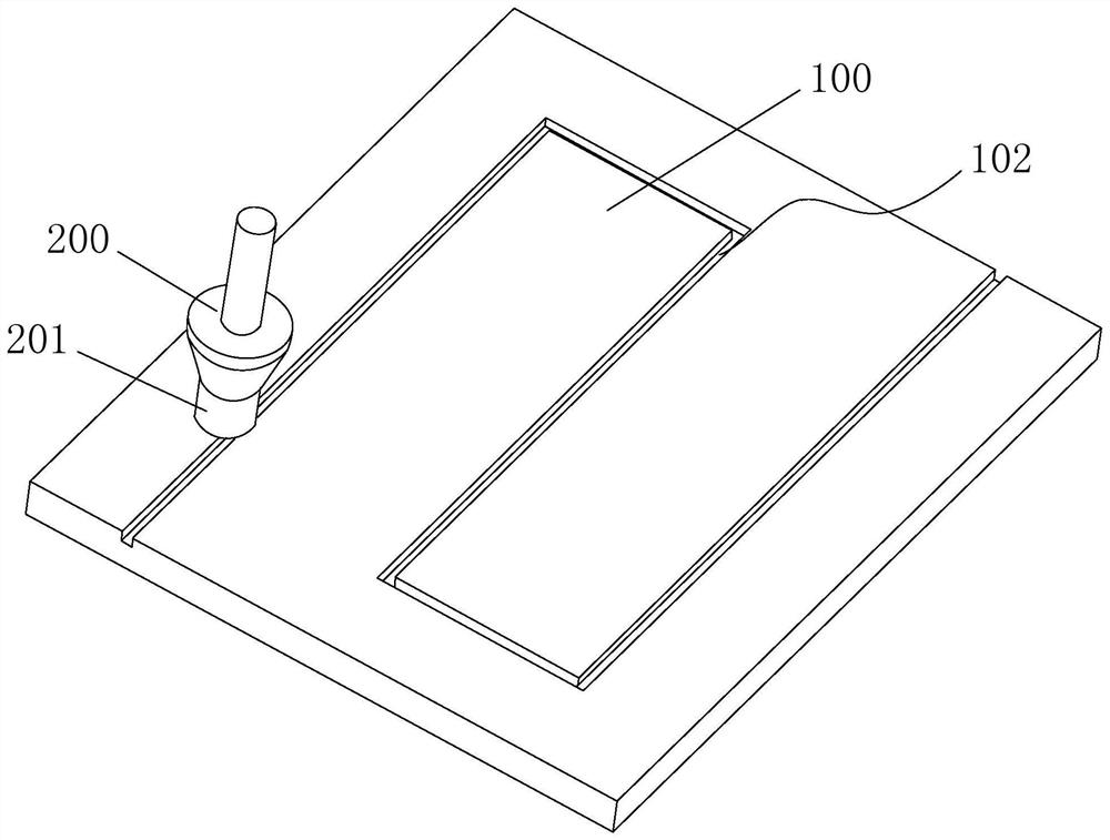
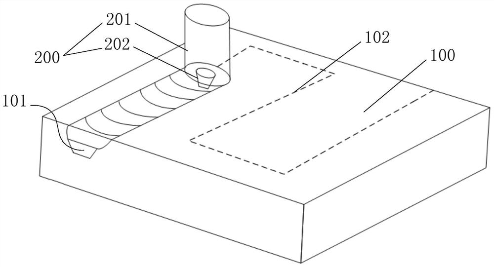
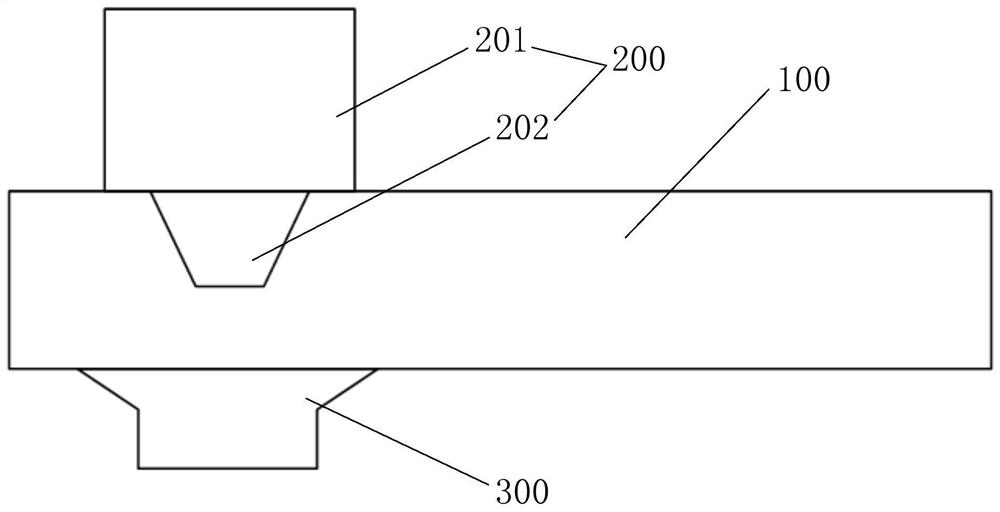
[0032] In order to explain the overall concept of the present invention, the following description will be described in detail by way of example.

[0033] In the description of the invention, it is to be understood that the terms "center", "upper", "lower", "front", "post", "left", "right", "vertical", "horizontal", The orientation relationship between "top", "bottom", "inside", "outside", "axial", "radial", "circumferential", etc., based on the orientation or positional relationship shown in the drawings, only It is to facilitate the description of the present invention and simplified description, rather than indicating or implying that the device or element must have a specific orientation, and is constructed in a particular orientation, and thus is not to be construed as limiting the invention.

[0034] Moreover, the term "first", "second" is used only for the purpose of describing, and cannot be understood as an indication or implicit relative importance or implicitting the nu...


PUM


Abstract

The invention discloses an ultrasonic-assisted stirring friction tunnel forming method. The method comprises the following steps of: machining a groove on the surface of a workpiece of a to-be-machined tunnel along a tunnel extending path; clamping and fixedly placing the workpiece on a working table, and enabling a notch of the groove to face upwards; positioning a stirring head of stirring friction welding equipment right above the notch at one end of the groove of the workpiece, enabling an inclination angle ranging from 0 degree to 4 degrees to be formed between the axis of the stirring head and the normal of the surface of the workpiece, and coaxially arranging an ultrasonic amplitude-change pole, an ultrasonic generator and the stirring head; starting a spindle of the stirring friction welding equipment to drive the stirring head to rotate, enabling the stirring head to penetrate through the groove in the vertical downward direction to be inserted into the workpiece, then starting the ultrasonic generator, and enabling the stirring head to stay for preset time; and driving the stirring head and the ultrasonic amplitude-change pole to take the synchronous translational motionalong an extending path of the groove, forming a tunnel in the workpiece, and when the stirring head and the ultrasonic amplitude-change pole take the translational motion to the other end of the groove, completing formation of the tunnel.

Description

Technical field [0001] The present invention relates to the field of stirring friction processing, and more particularly to an ultrasonic assisted stirring friction tunnel forming method. Background technique [0002] With the development of equipment integration, conventional heat dissipation winders are difficult to place in the integrated equipment, and the cooling efficiency of the fan is difficult to achieve rapid cooling. The medium cooling has a high heat conversion efficiency, which has been widely used in battery packs, engines, and baking boxes. [0003] At present, the cooling medium is used for water-cooled, and some are transmitted by the hose to take away the amount of heat; however, the hose requires a complex cable and auxiliary fixture, and there are more soft layers in the equipment. The tube will bring a certain difficult to detect and maintenance of the equipment, and the fixation of the hose will increase more, and the maintenance and maintenance of the post-...

Claims


Application Information

Patent Timeline
Patent Type & Authority Applications(China)
IPC IPC(8): B23K20/12B23K20/26
CPCB23K20/12B23K20/1255B23K20/26
Inventor 万龙刘景麟黄体方
Owner 昆山万洲特种焊接有限公司
Why Eureka
Try Eureka