


Quick Research
Generate reliable direction feasibility study reports for your R&D in just a few steps.

Technical Q&A
Discover and master advanced knowledge NOW. Basics, ideas, possibilities, all at once.

Find Solutions
As an expert in R&D theories, this can generate solutions to your technical problems instantly.

Evaluate Feasibility
Analyze your overall solution with one click, know your potential R&D risks in advance.

Monitor Landscape
Get weekly tech updates, stay abreast of the latest tech innovations and key insights.
Vacuum precision casting furnace formwork lifting device
A technology of precision casting and mold shell, applied in the field of metallurgy, can solve problems such as high personnel requirements and unfavorable product uniformity, and achieve the effect of improving uniformity, shortening production cycle, and improving fast and accurate positioning.
- Summary
- Abstract
- Description
- Claims
- Application Information
AI Technical Summary
Problems solved by technology
Method used
Image

Examples
no. 1 example ;
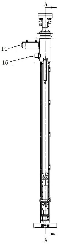
[0073] like figure 1 combine figure 2 Shown, the present invention a kind of vacuum investment casting furnace formwork hoisting device, comprises:
[0074] Fixing piece 1, which passes through and is fixed on the bottom wall of the ingot cavity;
[0075] Main shaft 2, one end of which penetrates into the fixed part 1, and the other end is located outside the ingot cavity, which can move vertically in the fixed part 1 deep into or withdrawn from the ingot cavity;
[0076] The first sealing assembly is located in the ingot cavity and arranged between the fixed part 1 and the main shaft 2;
[0077] The second sealing assembly, which is located in the ingot cavity, is fixed between the fixing part 1 and the high temperature resistant telescopic protective cover 21;
[0078] Support frame 7, which is located outside the ingot cavity, is arranged in a vertical direction, and its upper part is fixed on the fixture 1;
[0079] The power source 14 is fixed on the top of the suppo...
no. 2 example ;
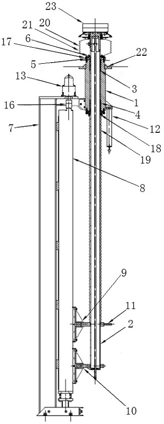
[0091] continue to refer figure 1 combine figure 2 Shown, the present invention a kind of vacuum investment casting furnace formwork hoisting device, comprises:
[0092] Fixing piece 1, which passes through and is fixed on the bottom wall of the ingot cavity;
[0093] Main shaft 2, one end of which penetrates into the fixed part 1, and the other end is located outside the ingot cavity, which can move vertically in the fixed part 1 deep into or withdrawn from the ingot cavity;
[0094] The first sealing assembly is located in the ingot cavity and is arranged between the fixed part 1 and the main shaft 2, including the sealing ring positioning gasket 3 fixed in the fixed part 1 and the shaft sealing ring 4, and sleeved on the fixed part 1 The dust-proof sealing ring 18 of two ports, the dust-proof ring retaining ring 6 covers are contained on the dust-proof sealing ring 18;
[0095] The second sealing assembly, which is located in the ingot cavity, is fixed between the fixed...
PUM
 Abstract
Description
Claims
Application Information
 - R&D Engineer
- R&D Manager
- IP Professional
- Industry Leading Data Capabilities
- Powerful AI technology
- Patent DNA Extraction
Browse by: Latest US Patents, China's latest patents, Technical Efficacy Thesaurus, Application Domain, Technology Topic, Popular Technical Reports.
© 2024 PatSnap. All rights reserved.Legal|Privacy policy|Modern Slavery Act Transparency Statement|Sitemap|About US| Contact US: help@patsnap.com