Auxiliary intelligent heat dissipation device for new-energy street lamp

A heat dissipation device and new energy technology, applied in the field of electric light sources, can solve the problems of affecting the service life of LED street lamps, the service life of LED lamps, and prone to traffic accidents, and achieve convenient cooling and heat dissipation, accelerated air flow speed and flow effect, The effect of improving the service life

Active Publication Date: 2021-03-16
海宁康铭照明电器有限公司
View PDF5 Cites 2 Cited by
  • Summary
  • Abstract
  • Description
  • Claims
  • Application Information

AI Technical Summary

Problems solved by technology

[0002] Electric light source is a general term for the settings that emit light with electric energy. Common electric light source devices mainly include incandescent lamps and LED lamps; LED lamps are widely used due to their excellent performance, but LED lamps are greatly affected by temperature during operation. , in high temperature environment, the service life of LED lights will be seriously affected
[0003] However, during the use of the existing LED street lamps, heat dissipation is only performed by opening heat dissipation holes, and the heat dissipation effect is poor. It is always connected with the outside world, making it easy for external dust to enter the interior of the lamp body, which greatly affects the service life of the LED street lamp, and is likely to cause lamp body failure, make the road lose illumination, and cause traffic accidents easily

Method used


Image

  • Auxiliary intelligent heat dissipation device for new-energy street lamp
  • Auxiliary intelligent heat dissipation device for new-energy street lamp
  • Auxiliary intelligent heat dissipation device for new-energy street lamp

Examples


Embodiment Construction

[0028] The following will clearly and completely describe the technical solutions in the embodiments of the present invention with reference to the accompanying drawings in the embodiments of the present invention. Obviously, the described embodiments are only some, not all, embodiments of the present invention. Based on the embodiments of the present invention, all other embodiments obtained by persons of ordinary skill in the art without making creative efforts belong to the protection scope of the present invention.

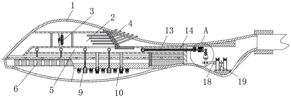
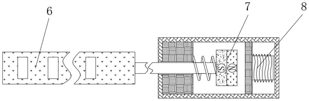
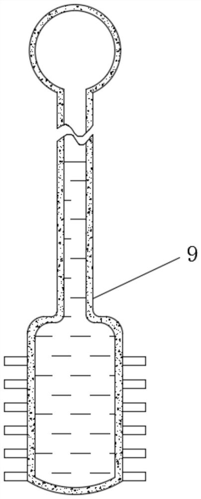
[0029] see Figure 1-5 , a new energy street lamp auxiliary intelligent heat dissipation device, including a lamp body 1, an air inlet 2, a fan 3, a cooling semiconductor 4, a working chamber 5, a sealing strip 6, a permanent magnet block 7, an electromagnetic push block 8, a heat dissipation pipe 9, and a guide Air pipe 10, sealing ball 11, outlet head 12, temperature sensing component 13, bimetal 14, threaded sleeve 15, connection block 16, control block 17,...


PUM


Abstract

The invention relates to the technical field of electric light sources, and discloses an auxiliary intelligent heat dissipation device for a new-energy street lamp. The auxiliary intelligent heat dissipation device comprises a lamp body. An air inlet is formed in the lamp body, a fan and a refrigeration semiconductor are arranged in the air inlet, and a working cavity is formed in the bottom of the air inlet. A sealing strip is movably connected to the interior of the working cavity, a permanent magnet block is fixedly connected to the exterior of the sealing strip, and an electromagnetic pushblock is movably connected to the exterior of the permanent magnet block. Heat dissipation pipes and air guide pipes are arranged in the working cavity, and a temperature sensing assembly is arrangedat the inner top of the working cavity. Through the cooperative use of the temperature sensing assembly, a bimetallic strip, a threaded sleeve, a connecting block, a control block, an ejecting rod and electric contact blocks, the effect of intelligently controlling the equipment to start automatic heat dissipation is achieved, the use effect of the device is effectively improved, it is avoided that the heat dissipation work is still conducted in a low-temperature environment, and the waste of energy is effectively reduced.

Description

technical field [0001] The invention relates to the technical field of electric light sources, in particular to an auxiliary intelligent heat dissipation device for new energy street lamps. Background technique [0002] Electric light source is a general term for the settings that emit light with electric energy. Common electric light source devices mainly include incandescent lamps and LED lamps; LED lamps are widely used due to their excellent performance, but LED lamps are greatly affected by temperature during operation. , In a high temperature environment, the service life of LED lights will be seriously affected. [0003] However, during the use of the existing LED street lamps, heat dissipation is only performed by opening heat dissipation holes, and the heat dissipation effect is poor. It is always connected with the outside world, making it very easy for external dust to enter the interior of the lamp body, which greatly affects the service life of the LED street l...

Claims


Application Information

Patent Timeline
Patent Type & Authority Applications(China)
IPC IPC(8): F21V29/54F21V29/67F21V29/71F21V29/83F21Y115/10F21W131/103
CPCF21W2131/103F21V29/54F21V29/67F21V29/71F21V29/83F21Y2115/10
Inventor 王忠伟
Owner 海宁康铭照明电器有限公司
Why Eureka
Try Eureka