
Pintle injector and liquid rocket engine

An injector and needle bolt technology, which is applied in the field of liquid rocket engines, can solve problems such as high processing and equipment precision requirements, and achieve the effects of low processing and maintenance costs, low processing and assembly precision requirements, and reduced non-uniformity.

Active Publication Date: 2021-03-16
NAT UNIV OF DEFENSE TECH
View PDF5 Cites 3 Cited by
  • Summary
  • Abstract
  • Description
  • Claims
  • Application Information

AI Technical Summary

Problems solved by technology

[0004] Based on this, it is necessary to provide a pintle injector and a liquid rocket engine for the problem that the traditional pintle injector requires high processing and equipment precision.

Method used


Image

  • Pintle injector and liquid rocket engine
  • Pintle injector and liquid rocket engine
  • Pintle injector and liquid rocket engine

Examples


Embodiment Construction

[0019] In order to make the above objects, features and advantages of the present invention more comprehensible, specific implementations of the present invention will be described in detail below in conjunction with the accompanying drawings. In the following description, numerous specific details are set forth in order to provide a thorough understanding of the present invention. However, the present invention can be implemented in many other ways different from those described here, and those skilled in the art can make similar improvements without departing from the connotation of the present invention, so the present invention is not limited by the specific embodiments disclosed below.

[0020] The terms "first" and "second" are used for descriptive purposes only, and cannot be understood as indicating or implying relative importance or implicitly specifying the quantity of indicated technical features. Thus, the features defined as "first" and "second" may explicitly or ...


PUM


Abstract

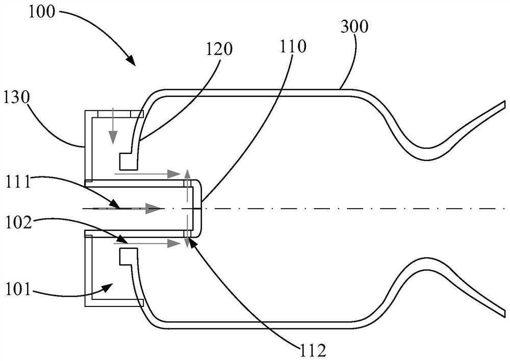
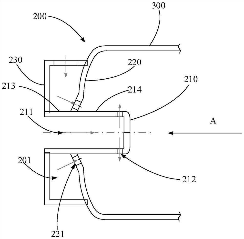
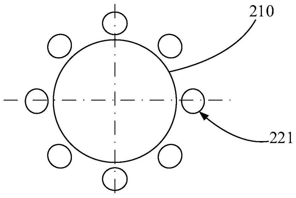
The invention relates to a pintle injector and a liquid rocket engine. The pintle injector comprises a panel, a cover body and a pintle. The panel is provided with a first inner hole. The cover body is connected with the panel, and a second inner hole opposite to the first inner hole in a spaced manner is formed in the cover body. The pintle is arranged in the first inner hole and the second innerhole in a penetrating manner, the pintle is in sealing fit with the hole wall of the first inner hole and the hole wall of the second inner hole, and the pintle, the cover body and the panel are in cooperation to form a collection cavity. The pintle is provided with an inner flowing channel, the circumferential side of the pintle is provided with an injection part communicating with the inner flowing channel, the injection part is located outside the collection cavity, multiple first injection holes are formed in the side wall, close to the injection part, of the collection cavity, and the first injection holes are evenly formed around the axis of the pintle at intervals. The pintle comprises a first section and a second section connected with the first section, the first section cooperates with the panel and the cover body to form the collection cavity, the injection part is arranged on the circumferential side of the second section, and the first injection holes are opposite to theouter side wall of the second section.

Description

technical field [0001] The invention relates to the technical field of liquid rocket engines, in particular to a pintle injector and a liquid rocket engine. Background technique [0002] The liquid rocket engine converts the chemical energy in the propellant into kinetic energy through combustion, and is an indispensable power device for space transportation. In a liquid rocket engine, the liquid propellant enters the combustion chamber through the injector, and then the liquid oxidant and fuel are broken into droplets, evaporated into a gaseous state under high temperature conditions, and then undergo a chemical reaction to produce high-temperature gas, which is ejected through the nozzle Generate thrust. The injector determines the velocity, distribution and atomization of the propellant into the combustion chamber and therefore has a major impact on the performance of the engine. [0003] At present, pintle injectors have been widely used in liquid rocket engines becaus...

Claims


Application Information

Patent Timeline
Patent Type & Authority Applications(China)
IPC IPC(8): F02K9/52
CPCF02K9/52
Inventor 成鹏张彬白晓梁涛曹鹏进李清廉吴继平张家奇
Owner NAT UNIV OF DEFENSE TECH
Learn More