A uniform steam inlet/admission device for a steam turbine

A technology of steam turbine and steam intake, applied in the direction of machine/engine, mechanical equipment, engine components, etc., can solve the problems of lack of steam flow guide vanes, steam intake loss, loss, etc., to improve safety and stability, circumferential distribution Uniform, uniform flow velocity distribution

Active Publication Date: 2019-08-23
XI AN JIAOTONG UNIV
View PDF4 Cites 0 Cited by
  • Summary
  • Abstract
  • Description
  • Claims
  • Application Information

AI Technical Summary

Problems solved by technology

[0005] However, this type of spiral structure still has defects. On the one hand, during the steam flow process, due to the lack of separation and guidance of the steam guide vanes, the fluid flow separated from the main flow is uncontrollable, resulting in uneven distribution of the inlet steam along the circumferential direction. On the other hand, due to the uncontrollable flow rate of the separated fluid, the cross-sectional area of ​​the flow channel which decreases monotonically along the steam inlet direction cannot accurately adapt to the change of the steam volume, resulting in uneven flow velocity distribution of the steam on each section of the flow channel , there is an intake steam loss
Although the double-helix steam inlet structure has improved the single-helix steam inlet structure, it has not solved the problem of uneven circumferential distribution of the inlet steam in essence, and further optimization is needed

Method used


Image

  • A uniform steam inlet/admission device for a steam turbine
  • A uniform steam inlet/admission device for a steam turbine
  • A uniform steam inlet/admission device for a steam turbine

Examples


Embodiment Construction

[0031] The present invention will be further described below in conjunction with the accompanying drawings.

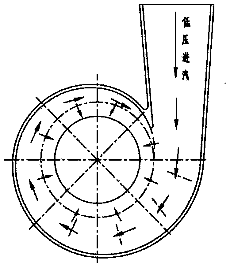
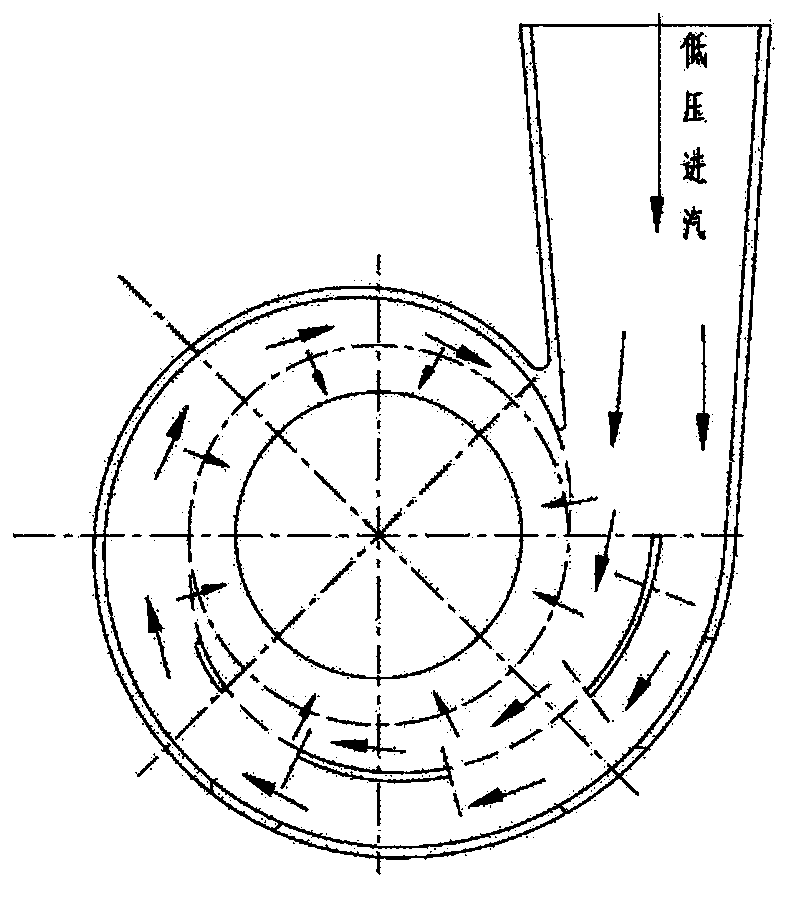
[0032] see Figure 4 to Figure 7 , a uniform steam inlet / admission steam device for a steam turbine provided by the present invention includes an annular steam inlet flow channel casing and an inlet steam pipe casing 1 communicating with the steam inlet flow path casing; wherein, the The steam inlet channel 5 of the steam channel housing is arranged axially symmetrically, and the cross-sectional area of ​​the steam inlet channel 5 decreases monotonically along the direction of the steam inlet flow, and the steam inlet pipe housing 1 communicates with the largest cross-sectional area of ​​the steam inlet channel 5 , and a number of steam guide vanes 4 are arranged axially symmetrically on the inner wall of the steam inlet channel 5 of the steam channel housing.

[0033]Specifically, the air flow guide vane 4 includes a first air flow guide vane, a second air flow guide...


PUM


Abstract

The invention discloses a uniform steam inlet / admission device for a steam turbine, which comprises an annular steam inlet flow path casing and a steam inlet pipe casing connected with the steam inlet flow path casing; wherein, the steam flow The steam inlet channel of the channel shell is arranged axially symmetrically, and the cross-sectional area of ​​the steam inlet channel decreases monotonously along the direction of the steam inlet flow. A plurality of steam flow guide vanes are arranged axially symmetrically on the inner wall of the steam inlet channel of the channel housing. The present invention proceeds from the two angles of reducing the loss of the inlet steam and the impact of the steam flow on the rotor, adopts the design of the chamber with a variable cross-section to adapt to the change of the flow rate of the steam in the flow process, and makes the steam flow in each inlet channel. The flow velocity distribution of the cross-section tends to be uniform, reducing the pressure and temperature loss of the inlet steam, and improving the efficiency of the steam turbine; by rationally arranging the steam guide vanes, the distribution of the inlet steam in the circumferential direction tends to be uniform, and the impact of the inlet steam on the rotor is reduced. The steam flow force improves the safety and stability of the unit operation.

Description

technical field [0001] The invention belongs to the technical field of design of a steam inlet / steam supplement chamber of a medium and low pressure steam turbine, and in particular relates to a uniform steam intake / steam supplement device for a steam turbine. Background technique [0002] A steam turbine is a turbine that uses steam as its medium, and its main purpose is to convert the heat energy carried by the steam into the mechanical energy of the internal rotating parts. High-power steam turbines are one of the key power equipment in the construction of modern large-scale power plants. Improving the efficiency of steam turbines can significantly improve the operating efficiency of power plants and reduce losses. In the total loss of the steam turbine, the loss of inlet steam / admission steam accounts for a relatively large proportion and cannot be ignored. Therefore, if the inlet steam loss can be reduced, the efficiency of the steam turbine can be effectively improved...

Claims


Application Information

Patent Timeline
Patent Type & Authority Patents(China)
IPC IPC(8): F01D9/04
CPCF01D9/041F01D9/047F05D2240/12F01D9/048F01D9/026F05D2220/31
Inventor 袁奇潘阳黄超
Owner XI AN JIAOTONG UNIV
Why Eureka
Try Eureka