
Pull rod type multipurpose steel trestle abutment and construction method thereof

A construction method and multi-purpose technology, applied in the direction of bridges, bridge parts, bridge construction, etc., can solve the problems of complex concrete stress, difficulty in demolition, high cost, etc., achieve high-quality and stable design and construction, and small subsequent settlement , good effect

Pending Publication Date: 2021-03-12
CCTEB INFRASTRUCTURE CONSTR CO LTD +1
View PDF9 Cites 1 Cited by
  • Summary
  • Abstract
  • Description
  • Claims
  • Application Information

AI Technical Summary

Problems solved by technology

[0003] In order to overcome the technical defects of the traditional steel trestle bridge construction in the prior art, such as complicated concrete stress, large volume, difficulty in breaking it later, and high cost, the present invention provides a tie-rod multi-purpose steel trestle abutment and its construction method, which can meet relatively high demands. The need for high-fill abutments, high construction efficiency, can effectively reduce the number of repairs of abutments and shorten the span of steel trestles, and solve the above technical problems

Method used


Image

  • Pull rod type multipurpose steel trestle abutment and construction method thereof
  • Pull rod type multipurpose steel trestle abutment and construction method thereof
  • Pull rod type multipurpose steel trestle abutment and construction method thereof

Examples


Embodiment Construction

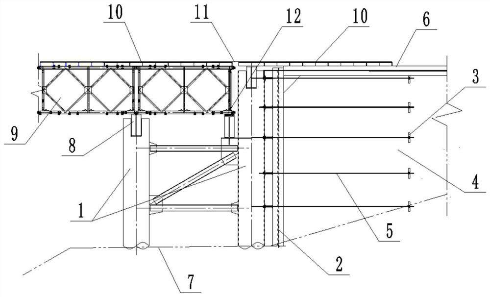
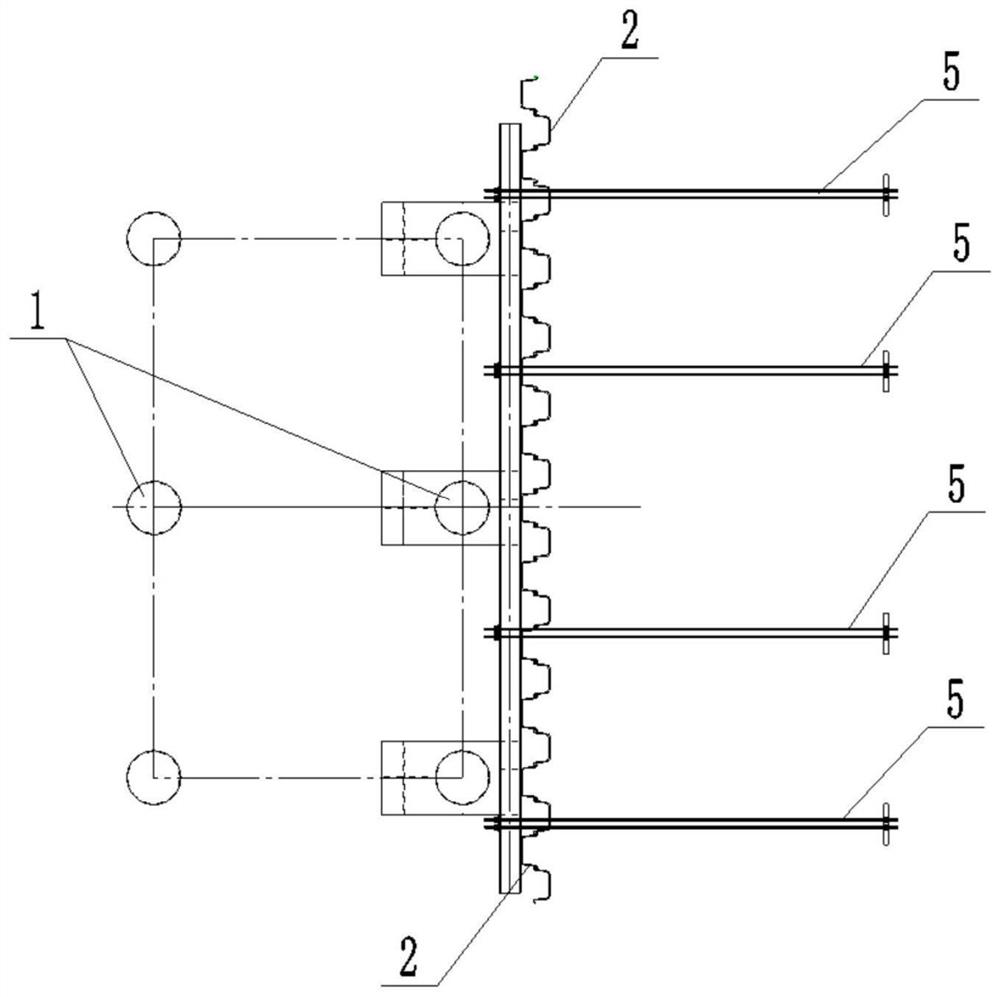
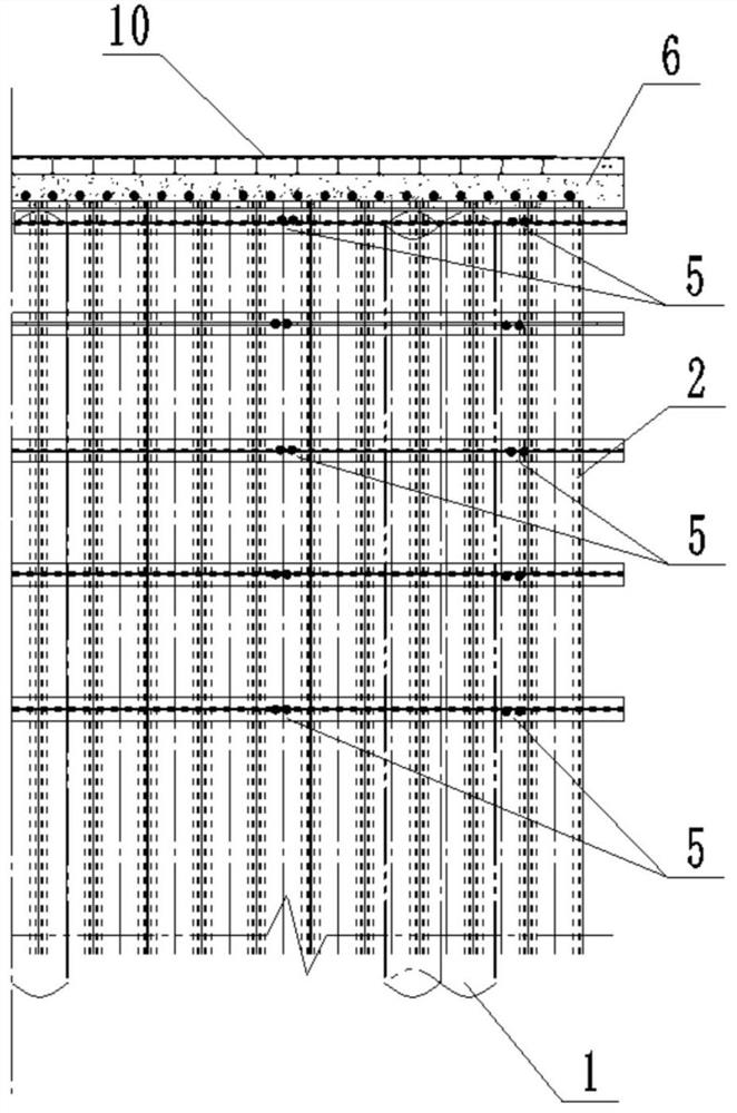
[0022] Such as Figure 1 to Figure 3 As shown, it is a schematic diagram of the longitudinal section, lower plane and 1 / 2 longitudinal section of a pull-rod type multi-purpose steel trestle abutment of the present invention, including double-row steel pipe piles 1, soil retaining steel sheet piles 2, reverse tension steel sheets 3, Abutment back filler 4, pull screw 5 and abutment strapping plate 6.

[0023] The double-row steel pipe pile 1 is a double-row steel pipe pile 13 with a spacing of 3m set according to the width of the trestle bridge. Round steel pipes or I-beams are arranged between the steel pipe piles 13 as the double-row steel pipe pile connection system 14, and the interior is filled with fine sand. Or concrete to enhance its rigidity and lateral stability, such as Figure 4 As shown, it is a detailed schematic diagram of the overlapping platform of the steel pipe pile 13 of the present invention.

[0024] The soil retaining steel sheet pile 2 is composed of a...


PUM


Abstract

The invention discloses a pull rod type multipurpose steel trestle abutment and a construction method thereof. The pull rod type multipurpose steel trestle abutment comprises double rows of steel pipepiles, soil retaining steel sheet piles, counter-pull steel sheets, abutment back filler, opposite-pull screws and an abutment butt strap. The construction method comprises the steps that firstly, the double rows of steel pipe piles are driven in front of the abutment to serve as an overall braking measure; then, aiming at the condition that abutment back filling soil in a river overtopping areais high, on one hand, the steel sheet piles and waist beam structures are adopted for achieving soil blocking and scouring effects, and on the other hand, the opposite-pull screws and the counter-pullsteel sheets are adopted for achieving balance of soil pressure; and reinforcing soil is filled between the steel sheet piles and the counter-pull steel sheets to ensure the stability of the abutmentback, a layer of concrete bridgehead butt strap is arranged at the upper part, and internally-arranged steel bars are welded with the tops of the steel pipe piles into a whole. By the adoption of thebridge abutment design and the construction method thereof, the problems that a temporary bridge abutment of a higher fill in the river overtopping area is difficult to disassemble, large in settlingvolume, poor in stability, scoured on the abutment back and the like can be solved, temporary trestle elevation control, bridge road sequential connection and trestle length reduction are facilitated, and therefore the purpose of reducing construction cost is achieved.

Description

technical field [0001] The invention relates to the technical field of bridge engineering construction, in particular to a tie rod type multipurpose steel trestle abutment and a construction method thereof. Background technique [0002] At present, a wide river floodplain is often designed in the embankment. When the project crosses the embankment, a temporary steel trestle bridge needs to be built. The service period is based on the construction period of 2-5 years. In order to avoid the impact on the steel trestle bridge during the flood period, the steel trestle bridge may be designed to The floodplain is relatively high. If the steel trestle bridge is directly built to the embankment on both banks, then the traditional concrete abutment is connected with the sidewalk, the steel trestle bridge will consume a lot of money and the cost will be high; It is directly connected to the floodplain access road, and the bottom of the concrete abutment needs to be equipped with a fo...

Claims


Application Information

Patent Timeline
IPC IPC(8): E01D19/02E01D21/00E02D5/04E02D5/28
CPCE01D19/02E01D21/00E02D5/04E02D5/28
Inventor 王少兵李洪松石九州叶亦盛李建勇解鑫鹏温盼闯
Owner CCTEB INFRASTRUCTURE CONSTR CO LTD
Learn More