
Alignment method of SE imbricated cell printing system

A printing system and printing position technology, which is applied in printing, printing machines, rotary printing machines, etc., can solve the problems of increased probability of hidden cracks and decreased appearance quality of shingled batteries, simplifying the alignment process, preventing hidden cracks in slices, damage reduction effect

Active Publication Date: 2021-03-12
ZHEJIANG AIKO SOLAR ENERGY TECH CO LTD +2
View PDF7 Cites 1 Cited by
  • Summary
  • Abstract
  • Description
  • Claims
  • Application Information

AI Technical Summary

Problems solved by technology

However, although increasing the number of MARK points improves the printing accuracy to a certain extent, it will also increase the probability of hidden cracks and reduce the appearance quality of shingled batteries.

Method used


Image

  • Alignment method of SE imbricated cell printing system
  • Alignment method of SE imbricated cell printing system
  • Alignment method of SE imbricated cell printing system

Examples


Embodiment Construction

[0043] In order to make the object, technical solution and advantages of the present invention clearer, the present invention will be further described in detail below in conjunction with the accompanying drawings.

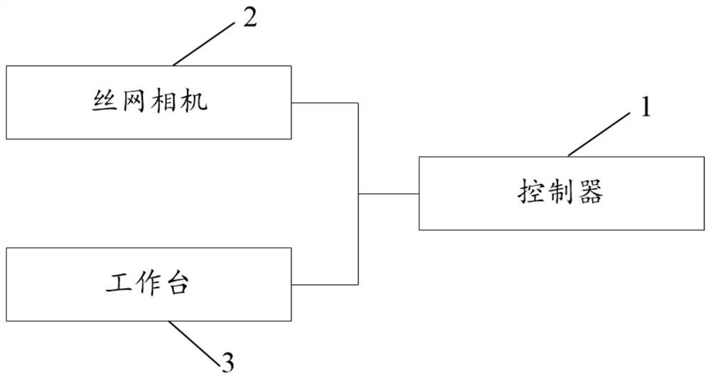
[0044] refer to figure 1 , as the first aspect of the present invention, the SE shingled battery electrode printing system includes a controller 1, a workbench 2 and a screen camera 3, and the screen camera 3 is arranged above the workbench 1; the silicon wafer 4 to be printed is placed on the workbench.

[0045] refer to figure 2 The front side of the silicon wafer 4 is provided with a plurality of sub-gate laser grooves 41 parallel to each other and three MARK points 42, and the three MARK points are distributed in a triangle. This distribution form can effectively determine the deviation between the silicon wafer 4 and the predetermined printing position. It provides a data basis for adjusting the placement angle of the silicon wafer 4 to ensure printing acc...


PUM


Abstract

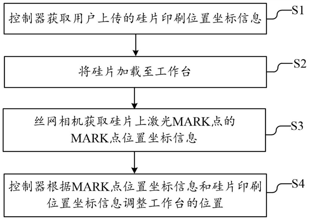
The invention discloses an alignment method of an SE imbricated cell printing system. The printing system comprises a controller, a workbench and a screen camera, and a silicon wafer to be printed isplaced on the workbench; and three MARK points are arranged on the surface of the silicon wafer, and the three MARK points are distributed in a triangular shape. The alignment method comprises the steps that the controller acquires silicon wafer printing position coordinate information uploaded by a user; the screen camera acquires MARK point position coordinate information of the MARK points on the silicon wafer; and the controller adjusts the position of the workbench according to the MARK point position coordinate information and the silicon wafer printing position coordinate information. By implementing the method, silk-screen printing positioning can be convenient, the appearance effect of the imbricated cell is optimized, and the hidden cracking probability of slices is reduced.

Description

technical field [0001] The invention relates to the technical field of crystalline silicon solar cell electrode printing, in particular to an alignment method for a SE shingled cell printing system. Background technique [0002] Shingled cells refer to cutting the redesigned grid lines into small cells with reasonable graphics, stacking and arranging each small cell, welding or bonding them into strings, and then laminating them into components after series-parallel typesetting. This allows the cells to be connected to each other in a more compact way. Under the same area, the laminated assembly can place more than 13% of the cells of the conventional assembly, and due to the optimization of the structure of this assembly, the design without welding strips greatly reduces the The line loss of the components greatly increases the output power of the components. However, when making shingled batteries, the battery sheets need to be cut, which will also cause certain defects s...

Claims


Application Information

Patent Timeline
Patent Type & Authority Applications(China)
IPC IPC(8): B41M1/12B41M1/26B41F15/08B41F15/14B41F15/16H01L23/544H01L31/18
CPCB41M1/12B41M1/26B41F15/08B41F15/16B41F15/14H01L31/1804H01L23/544Y02P70/50
Inventor 方志文林纲正陈刚
Owner ZHEJIANG AIKO SOLAR ENERGY TECH CO LTD
Learn More