Engine camshaft manufacturing and machining process

A processing technology and camshaft technology, applied in the direction of manufacturing tools, metal processing equipment, grinding racks, etc., can solve the problems of low grinding accuracy, low grinding efficiency, mechanical system can not work normally, etc., to improve grinding quality and Efficiency, ensure grinding quality and efficiency, and meet the effect of clamping and fixing needs

Inactive Publication Date: 2021-03-12
杭州佳顿智能科技有限公司
View PDF9 Cites 4 Cited by
  • Summary
  • Abstract
  • Description
  • Claims
  • Application Information

AI Technical Summary

Problems solved by technology

[0003] The camshaft needs to withstand periodic impact loads, so the working surface of the camshaft must have high dimensional accuracy and small surface roughness to meet the requirements of use, so grinding is a very important step in the production process of the camshaft At present, most factories use manual grinding. Due to the limitation of manual work, the operation is difficult, the grinding efficiency is low, the grinding accuracy is not high, and burrs are easily caused. The existence of burrs will cause the entire mechanical system to fail to work normally. , so that the reliability and stability are reduced, thereby affecting the product quality; for this reason, the invention provides a manufacturing process of the engine camshaft

Method used


Image

  • Engine camshaft manufacturing and machining process
  • Engine camshaft manufacturing and machining process
  • Engine camshaft manufacturing and machining process

Examples


Embodiment Construction

[0033] In order to make the technical means, creative features, goals and effects achieved by the present invention easy to understand, the present invention will be further elaborated below in conjunction with specific drawings. It should be noted that, in the case of no conflict, the embodiments and Features in the embodiments can be combined with each other.

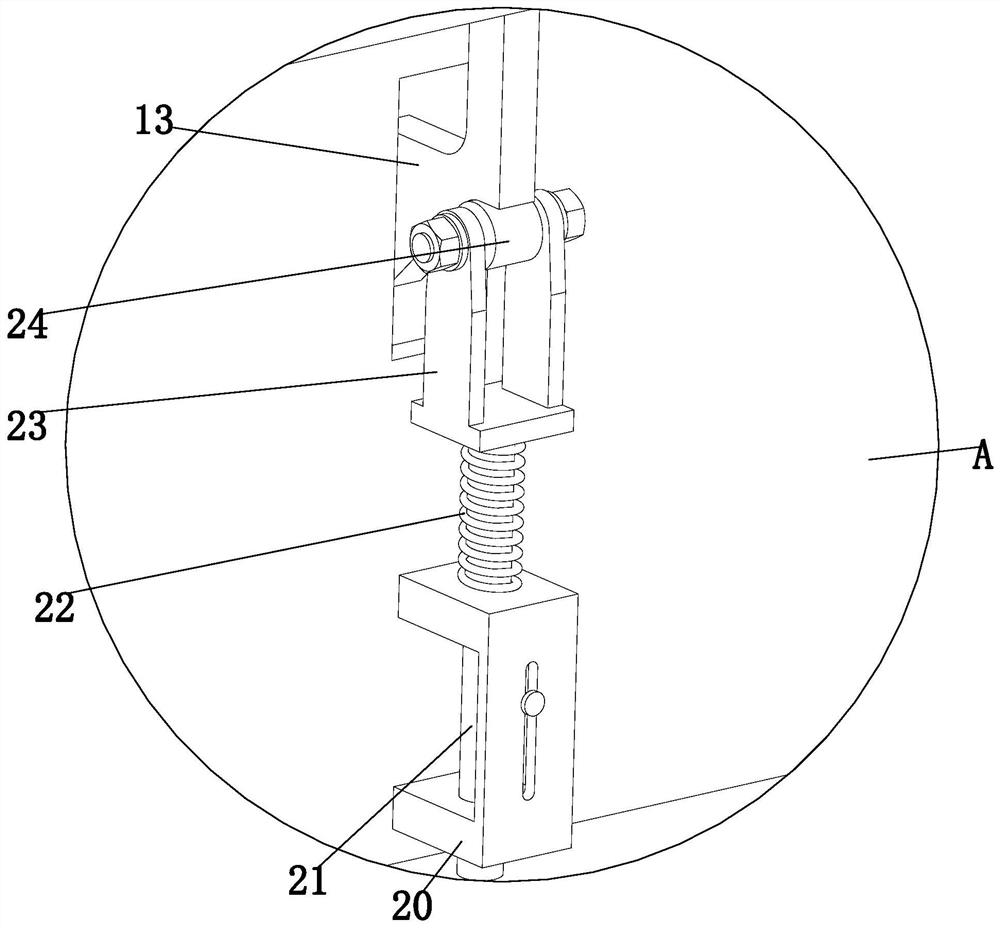
[0034] like Figure 1 to Figure 9 As shown, an engine camshaft manufacturing process uses engine camshaft manufacturing and processing equipment, and the manufacturing and processing equipment includes a pushing mechanism 1, a grinding mechanism 2, a clamping mechanism 3, a lifting mechanism 4 and a main beam vertical plate Frame 5, using the above-mentioned manufacturing and processing equipment to grind the camshaft of the steam engine, the specific method is as follows:

[0035] S1. Positioning of the camshaft: place the camshaft to be polished on the lifting mechanism 4 through a special fixture;

[0036] S2. Lift...


PUM


Abstract

The invention provides an engine camshaft manufacturing and machining process which comprises pushing mechanisms, polishing mechanisms, clamping mechanisms, lifting mechanisms and a main beam verticalplate frame. The pushing mechanisms are installed on the main beam vertical plate frame, the polishing mechanisms are arranged under the pushing mechanisms, and the polishing mechanisms are symmetrically installed on the outer wall of the main beam vertical plate frame; and the polishing mechanisms are connected with the pushing mechanisms in a rolling manner, the clamping mechanisms are arrangedunder the polishing mechanisms and symmetrically installed on the outer wall of the main beam vertical plate frame, and the lifting mechanisms are arranged under the clamping mechanisms and installedon the bottom end face of the main beam vertical plate frame. According to the engine camshaft manufacturing and machining process, the problems of high operation difficulty, low polishing efficiency, low polishing precision, easy generation of burrs, incapability of normal operation of the whole mechanical system due to existence of the burrs, reduced reliability and stability, influence on product quality and the like caused by polishing by adopting a manual manner in general factories are solved.

Description

technical field [0001] The invention relates to the technical field of engines, in particular to an engine camshaft manufacturing process. Background technique [0002] The car camshaft is an important part of the engine, and its function is to control the opening and closing of the valve; the main body of the camshaft is a cylindrical rod with approximately the same length as the cylinder group, and several cams are set on it to drive the valve. ; Camshafts are usually forged from high-quality carbon steel or alloy steel, and can also be cast with alloy cast iron or ductile iron; [0003] The camshaft needs to withstand periodic impact loads, so the working surface of the camshaft must have high dimensional accuracy and small surface roughness to meet the requirements of use, so grinding is a very important step in the production process of the camshaft ;At present, most factories use manual grinding. Due to the limitation of manual work, the operation is difficult, the gr...

Claims


Application Information

Patent Timeline
Patent Type & Authority Applications(China)
IPC IPC(8): B24B1/00B24B19/12B24B41/02B24B41/06B24B47/22
CPCB24B1/00B24B19/12B24B41/02B24B41/062B24B47/22
Inventor 郭庆营王嘉
Owner 杭州佳顿智能科技有限公司
Why Eureka
Try Eureka