
Polishing machine used for castings for elevator brake system and using method thereof

A technology for elevator brakes and grinding machines, which is applied to the cleaning method using gas flow, the cleaning method using tools, and the grinding frame, etc., which can solve the problems of inconvenient movement, troublesome replacement, and affecting the movement of grinding wheels The effect of saving time and effort during the moving process, simple and convenient movement, and simple and convenient replacement

Pending Publication Date: 2021-03-09
衡阳市群立新科机械有限公司
View PDF9 Cites 3 Cited by
  • Summary
  • Abstract
  • Description
  • Claims
  • Application Information

AI Technical Summary

Problems solved by technology

[0002] The grinding machine is a metallographic equipment used for rough grinding on the surface of the cut sample or the surface of the unprocessed sample. It can improve the quality and work efficiency of the sample. In the production process of the elevator, the elevator system The castings used in the dynamic system need to be polished and smoothed by a grinding machine after casting, but there are some problems in the use of some grinding machines now, and some small and medium-sized grinding machines are currently used due to their large size. It is inconvenient to move at times, and it is generally moved by manual handling. The moving process is time-consuming and laborious. At the same time, the grinding wheels on some current grinding machines need to be replaced frequently during use, but some current grinding machines need to be used when replacing the grinding wheels. Special tools are troublesome to replace, and the replacement process is time-consuming and laborious. In order to control the grinding accuracy of some current grinding machines, the handle on the grinding machine is used to drive the movement of the grinding wheel to control the grinding accuracy, but some grinding will occur during grinding. Debris, debris will accumulate and adhere to the slide rail, and some current grinding machines do not have a cleaning device for the slide rail. If the debris accumulated and attached to the slide rail of the grinding machine is not cleaned, it will affect the movement of the grinding wheel and affect the grinding

Method used


Image

  • Polishing machine used for castings for elevator brake system and using method thereof
  • Polishing machine used for castings for elevator brake system and using method thereof
  • Polishing machine used for castings for elevator brake system and using method thereof

Examples


Embodiment 1

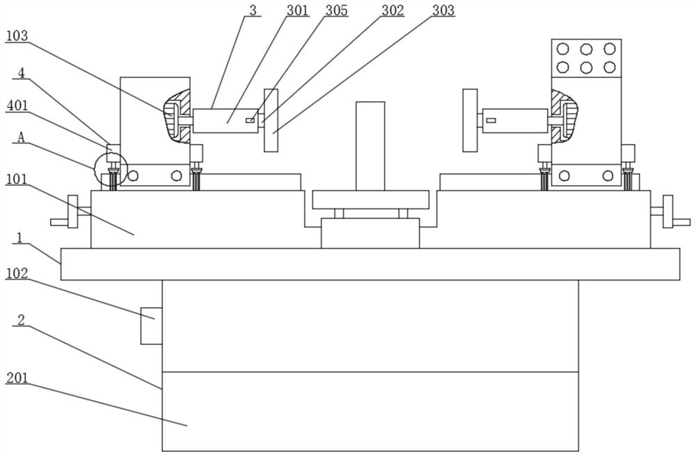
[0033] see Figure 1-6 , the present invention provides a technical solution:

[0034]A grinding machine for castings of an elevator braking system, comprising a main unit 1, a moving unit 2, a replacement unit 3 and a cleaning unit 4, the main unit 1 includes a body 101, a controller 102 and a first motor 103, the controller 102 It is fixedly connected with the body 101, the first motor 103 is fixedly connected with the body 101, the mobile device 2 includes a base 201, the base 201 is fixedly connected with the body 101, and the inner top of the left end surface of the base 201 is sleeved with a second motor 202, the second motor 202 The end of the main shaft is fixedly connected with a first threaded shaft 203, the right end of the first threaded shaft 203 is fixedly connected with a connecting shaft 204, the right end of the connecting shaft 204 is fixedly connected with a second threaded shaft 205, and the second threaded shaft 205 is rotationally connected with the base ...

Embodiment 2

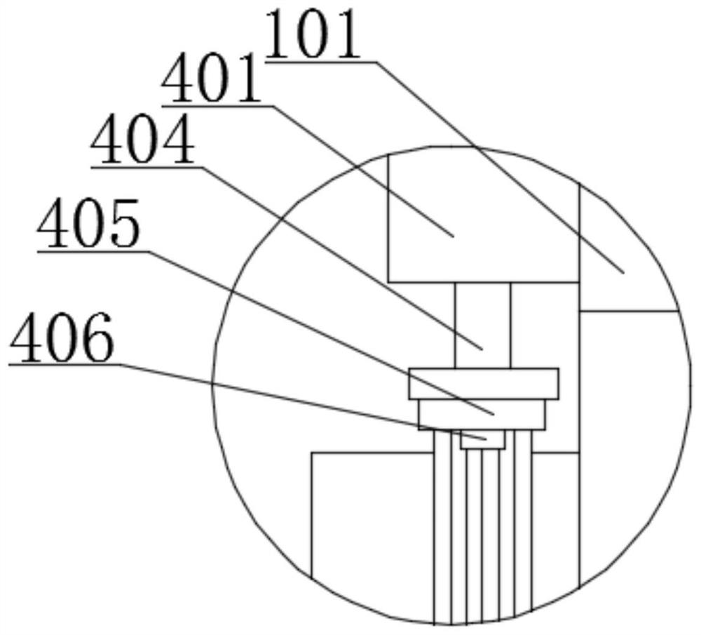
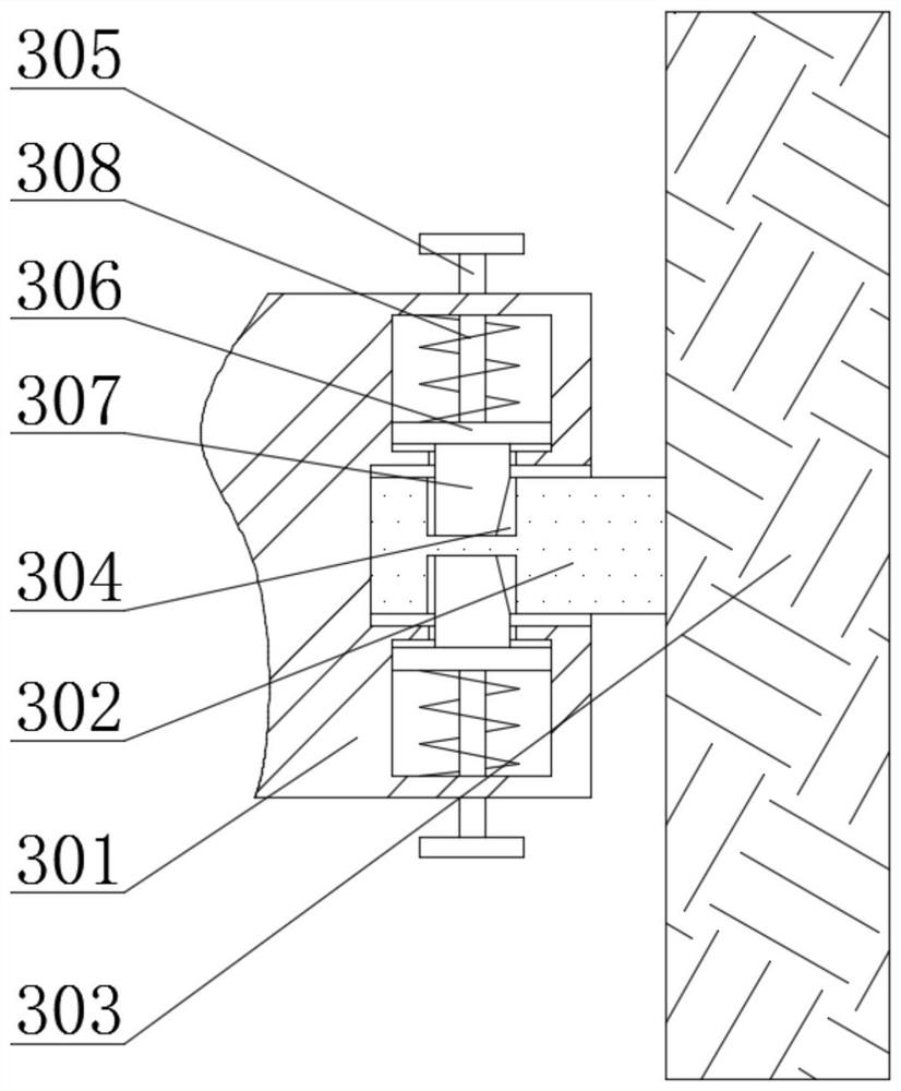
[0038] In embodiment 2, the same part as in embodiment 1 will not be repeated, please refer to the different parts image 3 , Figure 4 , Figure 5 , Figure 7 , Figure 8 with Figure 9 , the present invention provides a technical solution:

[0039] The cleaning device 4 includes a bellows 407, a support rod 409 and a filter screen 411, the bellows 407 is fixedly connected with the body 101, the bottom surface of the bellows 407 is connected with an air outlet pipe 408, the support rod 409 is fixedly connected with the bellows 407, and the bottom surface of the support rod 409 is fixedly connected There is a fan 410, a filter 411 runs through the bellows 407, and the filter 411 is slidably connected with the bellows 407. This setting is convenient for cleaning debris attached to the slide rail; Fixedly connected, the other end of the third spring 412 is fixedly connected with a block 413, the block 413 runs through the bellows 407, the block 413 is slidably connected wit...


PUM


Abstract

The invention relates to the field of elevator production, in particular to a polishing machine used for castings for an elevator brake system. The polishing machine comprises a main body device, a moving device, a replacement device and a cleaning device. The main body device comprises a machine body, a controller and a first motor; the controller is fixedly connected with the machine body; and the first motor is fixedly connected with the machine body. In the polishing machine, by arranging a second motor, a first threaded shaft, a second threaded shaft and a push plate, in use, the second motor is controlled by the controller to rotate; the second motor rotates to drive the first threaded shaft to rotate; the first threaded shaft drives the second threaded shaft to rotate through a connecting shaft; the first threaded shaft and the second threaded shaft drive first sliders to slide respectively; the first sliders drive the push plate to slide through a rotating plate; the push plateslides to drive wheels to move, so that the wheels stretch out from the interior of a base; and the machine body is pushed to move the polishing machine. Therefore, the polishing machine is easy andconvenient to move, and the moving process saves both time and labor.

Description

technical field [0001] The invention relates to the field of elevator production, in particular to a grinding machine for castings of an elevator braking system and a method for using the same. Background technique [0002] The grinding machine is a metallographic equipment used for rough grinding on the surface of the cut sample or the surface of the unprocessed sample. It can improve the quality and work efficiency of the sample. In the production process of the elevator, the elevator system The castings used in the dynamic system need to be polished and smoothed by a grinding machine after casting, but there are some problems in the use of some grinding machines now, and some small and medium-sized grinding machines are currently used due to their large size. It is inconvenient to move at times, and it is generally moved by manual handling. The moving process is time-consuming and laborious. At the same time, the grinding wheels on some current grinding machines need to b...

Claims


Application Information

Patent Timeline
Patent Type & Authority Applications(China)
IPC IPC(8): B24B27/00B24B41/02B24B55/06B24B47/00B24B41/04B24B45/00B24B55/00B24B1/00B08B5/02B08B1/00
CPCB24B27/0007B24B41/02B24B55/06B24B47/00B24B41/04B24B45/003B24B55/00B24B1/00B08B5/02B08B1/30B08B1/12
Inventor 陈洋宁灿刘少江蒋春辉
Owner 衡阳市群立新科机械有限公司
Learn More