
Phase change radiator with liquid storage structure

A liquid storage structure and heat sink technology, which is applied in the construction parts of electrical equipment, cooling/ventilation/heating transformation, electrical components, etc., can solve the problem of high surface temperature of heat dissipation chips, achieve stable temperature and avoid overheating Effect

Pending Publication Date: 2021-03-05
周哲明
View PDF0 Cites 0 Cited by
  • Summary
  • Abstract
  • Description
  • Claims
  • Application Information

AI Technical Summary

Problems solved by technology

As a result, the surface temperature of the dissipated chip is higher

Method used


Image

  • Phase change radiator with liquid storage structure
  • Phase change radiator with liquid storage structure

Examples


Embodiment Construction

[0012] The present invention will be further described below in conjunction with the accompanying drawings and embodiments.

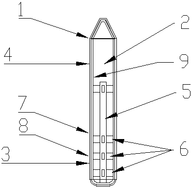
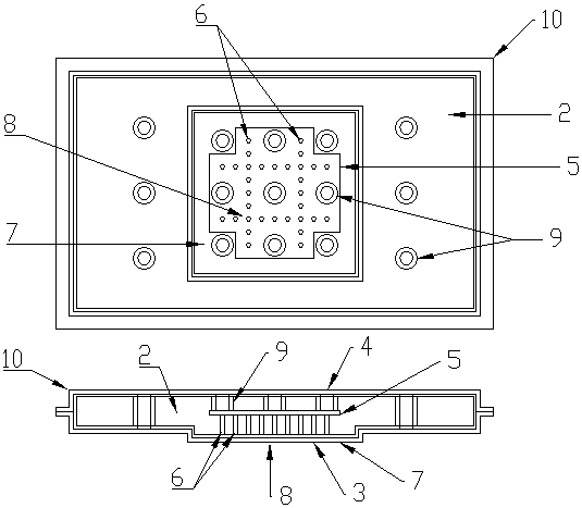
[0013] Such as figure 1 Shown: a heat pipe 1 with a liquid storage structure, a liquid storage structure 5 is installed between the evaporation end 3 and the condensation end 4 of the phase change chamber 2, the liquid storage structure 5 is a capillary porous structure, and one end of the liquid storage structure 5 There are multiple contact points 6 in contact with the evaporating end 3 , so that the liquid can directly flow back to each area of ​​the evaporating end 3 without returning to the core area 8 through the edge area 7 . One end of the liquid storage structure 5 is in contact with the liquid return channel 9 from the condensing end 4 to the evaporating end 3, and can replenish liquid.

[0014] Such as figure 2 Shown: a vapor chamber 10 with a liquid storage structure, a liquid storage structure 5 is installed between the evaporation end 3...


PUM


Abstract

The invention relates to electronic equipment, in particular to dissipation of heat generated by high-power electronic equipment such as a server, network equipment and a power battery. A phase changeradiator with a liquid storage structure is characterized in that the liquid storage structure is mounted between an evaporation end and a condensation end in a phase change cavity, the liquid storage structure is of a capillary porous structure, and one end of the liquid storage structure is provided with a plurality of contacts in contact with the evaporation end, so that liquid can directly flow back to each area of the evaporation end without flowing back to a core area through an edge area; therefore, liquid can be rapidly supplemented, all areas of the evaporation end can be subjected to evaporation heat dissipation continuously, and the situation that the temperature of local areas of the evaporation end is too high is avoided. A certain amount of liquid is stored in the liquid storage structure, the difference between the evaporation capacity and the condensation capacity when the instantaneous heat density rises can be effectively compensated for, the liquid at the evaporation end is continuously supplemented, and the temperature of the evaporation end is kept stable. One end of the liquid storage structure makes contact with the liquid backflow channel from the condensation end to the evaporation end, liquid can be supplemented, and a circulation path is formed.

Description

technical field [0001] The invention relates to electronic equipment, in particular to the dissipation of heat generated by high-power electronic equipment such as power batteries, servers, and network equipment. Background technique [0002] The heat pipe is a high-efficiency phase change radiator, which uses the phase change process of the liquid medium evaporating at the hot end and then condensing at the cold end to conduct heat quickly. The inside of the heat pipe is pumped into a negative pressure state and filled with a suitable liquid, which has a low boiling point and is easy to volatilize. The inner wall of the heat pipe has a capillary porous structure. One end of the heat pipe is the evaporating end, and the other end is the condensing end. When the evaporating end is heated, the liquid in the capillary structure vaporizes rapidly, and the vapor flows to the condensing end under the power of thermal diffusion, and condenses at the cold end to release heat. Alon...

Claims


Application Information

Patent Timeline
Patent Type & Authority Applications(China)
IPC IPC(8): H05K7/20
CPCH05K7/20327H05K7/20336
Inventor 周哲明
Owner 周哲明
Learn More