
Multimode control bias circuit

A bias circuit and resistor technology, applied in electrical components, parts of amplifying devices, high-frequency amplifiers, etc., can solve the problems of large power loss, complex circuit structure, complicated matching structure, etc., and achieve cost-effective and simple structure. Effect

Inactive Publication Date: 2021-03-02
泰新半导体(南京)有限公司
View PDF4 Cites 0 Cited by
  • Summary
  • Abstract
  • Description
  • Claims
  • Application Information

AI Technical Summary

Problems solved by technology

[0007] 1. The circuit structure is complex;
[0008] 2. The matching structure is cumbersome;
[0009] 3. Large power loss

Method used


Image

  • Multimode control bias circuit
  • Multimode control bias circuit

Examples


Embodiment Construction

[0028] The technical solutions in the embodiments of the present invention will be clearly and completely described below in conjunction with the accompanying drawings in the embodiments of the present invention. Obviously, the described embodiments are only some of the embodiments of the present invention, not all of them. Based on The embodiments of the present invention and all other embodiments obtained by persons of ordinary skill in the art without making creative efforts belong to the protection scope of the present invention.

[0029] In describing the present invention, it should be understood that the terms "upper", "lower", "front", "rear", "left", "right", "top", "bottom", "inner", " The orientation or positional relationship indicated by "outside", etc. is based on the orientation or positional relationship shown in the drawings, and is only for the convenience of describing the present invention and simplifying the description, rather than indicating or implying t...


PUM


Abstract

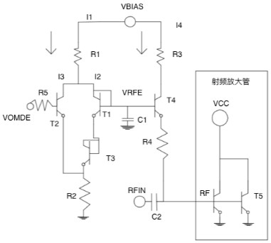
The invention discloses a multimode control bias circuit, and the circuit comprises a transistor T1, a transistor T2, a transistor T3, a transistor T4 and a radio frequency transistor; a collector electrode and a base electrode of the transistor T1 are interconnected, and a collector electrode and a base electrode of the transistor T3 are interconnected; the emitter of the transistor T1 is connected with the base of the transistor T3 and then connected with a resistor R2 in series to be grounded, the collector of the transistor T1 is connected with the collector of the transistor T2, the emitter of the transistor T2 is connected with the emitter of the transistor T3, and the base of the transistor T2 is connected with a resistor R5 in series and then connected into a voltage control circuit node VMODE. By combining the control voltage of the bias circuit and adjusting the size of the injection current of the bias circuit, the characteristic that the transconductance of the radio frequency transistor changes along with the size of the injection current is fully utilized, multi-mode control is achieved, the requirement of the multi-mode amplifier is met, and therefore the radio frequency amplifier has the advantages of being simple in structure and high in cost performance.

Description

technical field [0001] The invention relates to the technical field of radio frequency microwave semiconductor circuits, in particular to a multi-mode control bias circuit. Background technique [0002] The development of wireless communication technology promotes the continuous progress of RF front-end modules. In mobile communication and satellite communication terminals and other equipment, amplifier modules present multi-mode and multi-working frequency bands. [0003] At present, the mainstream technologies to realize this multi-mode and multi-band include: [0004] 1. Switching two or more amplifiers through a switch to achieve a variety of different output power modes; [0005] Second, optimize and reconstruct the output matching, and realize the output matching impedance transformation and frequency selection by means of switches. [0006] The above two types of methods have their own advantages and disadvantages, and their disadvantages are mainly reflected in the...

Claims


Application Information

Patent Timeline
Patent Type & Authority Applications(China)
IPC IPC(8): H03F1/02H03F3/19H03F3/21
CPCH03F1/0205H03F3/19H03F3/21
Inventor 王海军
Owner 泰新半导体(南京)有限公司
Learn More