


Quick Research
Generate reliable direction feasibility study reports for your R&D in just a few steps.

Technical Q&A
Discover and master advanced knowledge NOW. Basics, ideas, possibilities, all at once.

Find Solutions
As an expert in R&D theories, this can generate solutions to your technical problems instantly.

Evaluate Feasibility
Analyze your overall solution with one click, know your potential R&D risks in advance.

Monitor Landscape
Get weekly tech updates, stay abreast of the latest tech innovations and key insights.
Steel-concrete composite structure shear connector, construction method and shear composite structure
A technology of shear connectors and composite structures, which is applied in the fields of building construction connectors, steel-concrete composite structure shear connectors, and shear composite structures, and can solve problems such as residual tensile stress and unfavorable fatigue safety of beam components , to achieve the effect of ensuring fatigue performance, ensuring welding and processing quality, and fixing and stabilizing
- Summary
- Abstract
- Description
- Claims
- Application Information
AI Technical Summary
Problems solved by technology
Method used
Image

Examples
Embodiment 1
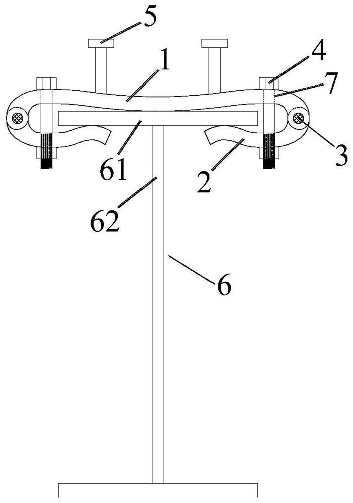
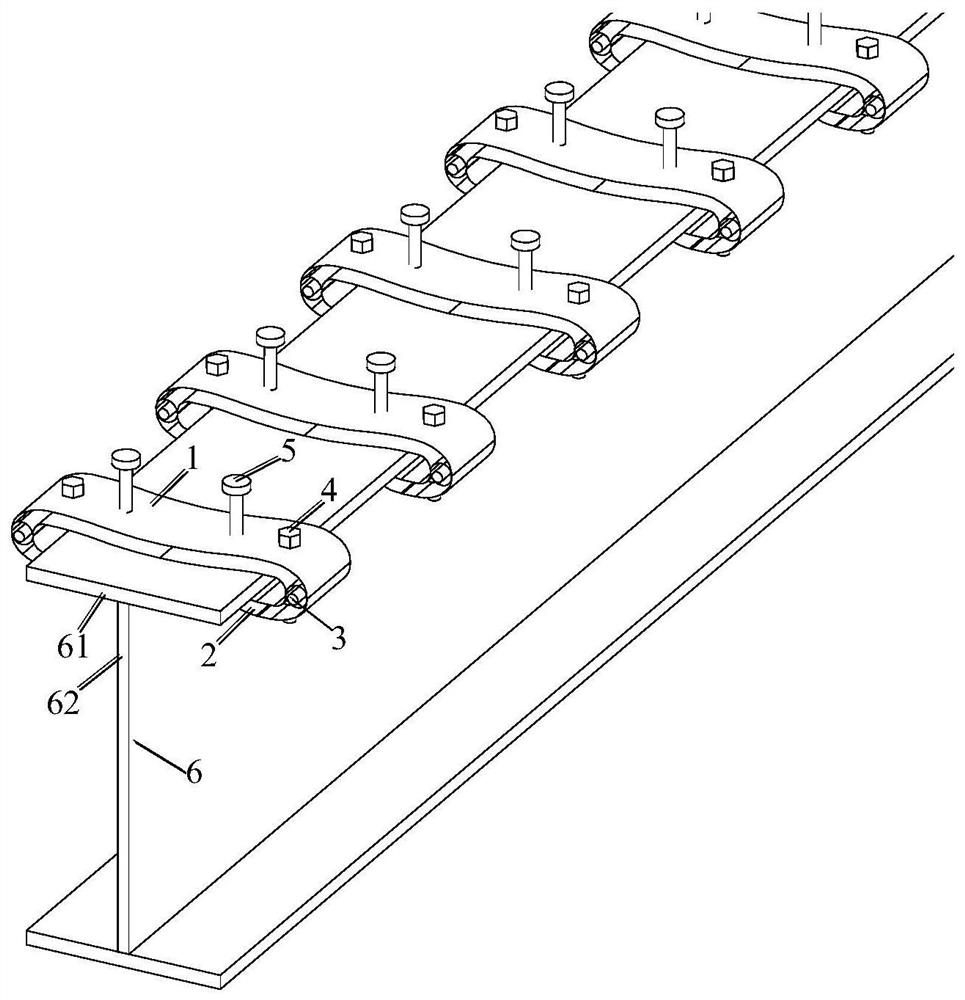
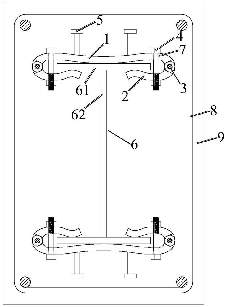
[0030] A steel-concrete composite structure shear connector, comprising an upper splint 1, a lower splint 2, a pin shaft 3, a high-strength bolt 4, a stud 5, and an H-shaped steel beam 6; each side of the upper splint 1 is connected to a The lower splint 2 is hinged, and the lower splint 2 is in the shape of a curved surface. After rotating inwardly around the hinge point, it encloses the flange 61 of the H-shaped steel beam 6; the upper splint 1 and the lower splint 2 are located on the wing. The corresponding parts on the outside of the edge 61 are connected and fastened by the high-strength bolts 4, so that the upper splint 1 and the lower splint 2 clamp the flange 61; Stud 5.
[0031] In this example, see Figure 1-4 , the middle part of the upper splint 1 has a downwardly concave radian, and the part corresponding to the high-strength bolt 4 has an upwardly convex radian, so that the gap between the upper splint 1 and the lower splint 2 at the corresponding part of the h...
Embodiment 2
[0043] In this embodiment, the part of the steel-concrete composite structure shear connector and its construction method are the same as the first embodiment.
[0044] For the part of the shear combined structure that is different from embodiment one, the specific description is as follows:
[0045] see Figure 4 , a shear composite structure, the above-mentioned steel-concrete composite structure shear connector is fixedly arranged on the flange 61 of the single end of the H-shaped steel beam 6, the upper splint 1, the stud 5, and the high-strength bolt 4 is pre-embedded and fixed in the concrete beam, so that the web 62 of the H-shaped steel beam is perpendicular to the concrete beam, and the flange 61 is attached to the concrete beam.
PUM
 Abstract
Description
Claims
Application Information
 - R&D Engineer
- R&D Manager
- IP Professional
- Industry Leading Data Capabilities
- Powerful AI technology
- Patent DNA Extraction
Browse by: Latest US Patents, China's latest patents, Technical Efficacy Thesaurus, Application Domain, Technology Topic, Popular Technical Reports.
© 2024 PatSnap. All rights reserved.Legal|Privacy policy|Modern Slavery Act Transparency Statement|Sitemap|About US| Contact US: help@patsnap.com