Measuring device and photolithography machine
A measurement device and quantity technology, applied in the field of lithography, can solve the problems of low stability of lithography machines, achieve the effects of reducing design and implementation difficulty, improving stability, and effectively cooling down
- Summary
- Abstract
- Description
- Claims
- Application Information
AI Technical Summary
Problems solved by technology
Method used
Image

Examples
Embodiment 1
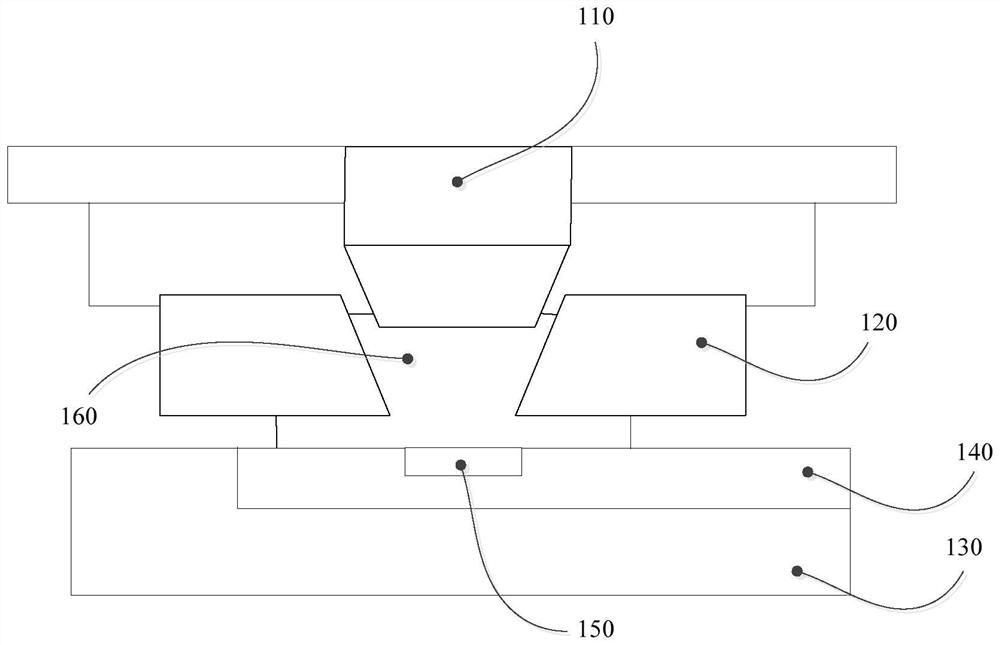
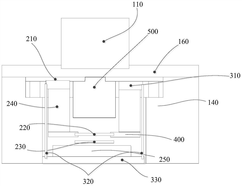
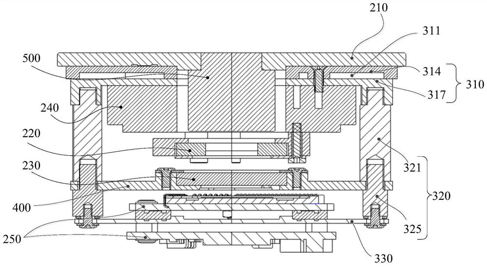
[0055] This embodiment provides a measuring device for detecting the polarization phase difference of the measuring light. refer to figure 2 , image 3 and Figure 4 , figure 2 It is a schematic structural diagram of the measurement device installed in the photolithography machine in Embodiment 1 of the present invention, image 3 is a schematic structural view of the measuring device in Embodiment 1 of the present invention, Figure 4 It is another structural schematic diagram of the measuring device 150 in the first embodiment of the present invention. The measuring device 150 includes a measuring body 210 , a wave plate 220 , a polarizing plate 230 , a rotary table 240 and an image acquisition and analysis unit 250 . The rotary table 240, the polarizer 230 and the image acquisition and analysis unit 250 are arranged on the measurement body 210, the rotary table 240 is used to drive the wave plate 220 to rotate, and the measurement light passes through the wave plate ...
Embodiment 2
[0083] This embodiment provides a measuring device 150 . The difference between the measuring device 150 in this embodiment and the measuring device 150 in Embodiment 1 is that in this embodiment, no cooling channel is provided in the first cooling member 310, and no cooling medium is provided in the first cooling member 310 , the third cooling member 330 is provided with a cooling channel, and a cooling medium is provided in the cooling channel.
[0084] refer to Figure 6 and Figure 7 , Figure 6It is a structural schematic diagram of the measuring device 150 in the second embodiment of the present invention, Figure 7 It is another structural schematic diagram of the measuring device 150 in the second embodiment of the present invention. The measuring device 150 includes a measuring body 210, a wave plate 220, a polarizing plate 230, a rotating table 240, an image acquisition and analysis unit 250 and a cooling assembly. The rotating table 240 , the polarizer 230 , the...
Embodiment 3
[0098] This embodiment provides a measuring device 150 . The difference between the measurement device 150 in this embodiment and the measurement device 150 in Embodiment 1 is that in this embodiment, cooling passages are also provided in the second cooling member 320 and the third cooling member 330, and there are cooling passages in the cooling passages. medium, the cooling passages in the first cooling element 310 , the second cooling element 320 and the third cooling element 330 communicate with each other.
[0099] refer to Figure 8 and Figure 9 , Figure 8 is a schematic structural view of the measuring device 150 in Embodiment 3 of the present invention, Figure 9 It is another schematic diagram of the structure of the measurement device 150 in the third embodiment of the present invention. The measurement device 150 includes a measurement body 210, a wave plate 220, a polarizer 230, a rotary table 240, an image acquisition and analysis unit 250 and a cooling assem...
PUM
 Abstract
Description
Claims
Application Information
 - R&D
- Intellectual Property
- Life Sciences
- Materials
- Tech Scout
- Unparalleled Data Quality
- Higher Quality Content
- 60% Fewer Hallucinations
Browse by: Latest US Patents, China's latest patents, Technical Efficacy Thesaurus, Application Domain, Technology Topic, Popular Technical Reports.
© 2025 PatSnap. All rights reserved.Legal|Privacy policy|Modern Slavery Act Transparency Statement|Sitemap|About US| Contact US: help@patsnap.com