Rotational flow exhaust device and system

An exhaust device and swirling technology, applied in the direction of smoke removal, cleaning methods and appliances, chemical instruments and methods, etc., can solve problems such as insufficient suction distance, pollutant escape, and poor collection effect of exhaust pipes. To achieve the effect of increasing the range of action, efficiently trapping pollutants, and avoiding the escape of pollutants

Active Publication Date: 2021-02-19
XI'AN UNIVERSITY OF ARCHITECTURE AND TECHNOLOGY
View PDF9 Cites 0 Cited by
  • Summary
  • Abstract
  • Description
  • Claims
  • Application Information

AI Technical Summary

Problems solved by technology

In actual operation, the converging effect of the suction of the exhaust pipe will rapidly decay in the environment. In addition, it is often disturbed by the ambient air flow or the suction distance is insufficient due to technological activities such as equipment blocking, resulting in the current capture of the local exhaust pipe. The collection effect is not good, and there is a large amount of pollutant escape

Method used


Image

  • Rotational flow exhaust device and system
  • Rotational flow exhaust device and system
  • Rotational flow exhaust device and system

Examples


Embodiment 1

[0059] This embodiment provides two design trapping strategies and exhaust modes, which are mode a and mode b respectively.

[0060] In mode a, for the working condition where the pollutants are greatly affected by the ambient wind, the rotation of the blades of the exhaust outlet of the exhaust pipe 1 generates a high radial velocity to effectively shield the ambient wind such as the side airflow, so that the pollutants are discharged from the air. The negative pressure area of ​​the air duct 1 is inhaled.

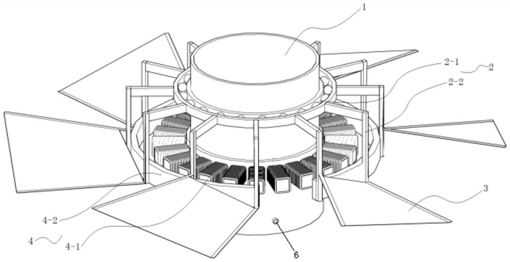
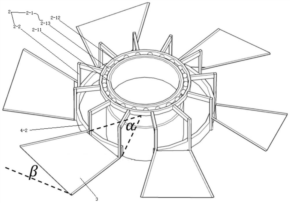
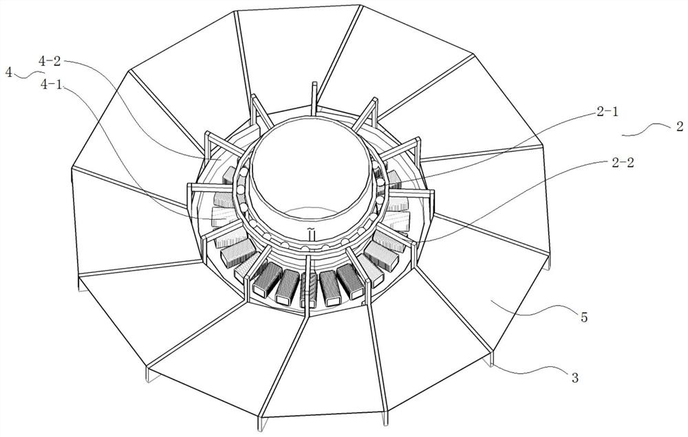
[0061] In order to realize above-mentioned technical task, the present invention is realized like this, as Figure 1-Figure 2 Shown:

[0062] The exhaust pipe 1 is located in the middle position, and the support ring assembly 2-1 (bearing) is welded on the periphery of the exhaust pipe 1, and the other side of the support ring assembly 2-1 (bearing) is glued to the blade through the connecting arm 2-2. The blades are made of plastic to ensure light structure, and the an...

Embodiment 2

[0067] This embodiment provides experimental verification for mode a and mode b, and compares the capture effect of commonly used traditional umbrella covers. The experimental results show that the present invention can effectively capture pollutants emitted in the environment. In this embodiment, CFD numerical simulation is used to carry out numerical experiments of fluid mechanics. This embodiment adopts the component transport model (Species transport). The component transport model can analyze the flow process of gas flow between different gas components in detail.

[0068] In this embodiment, the test environment is a small volatile workshop whose size is 2m long*2m wide*2m high. There is a high-temperature organic volatilization barrel 7 in the center of the room, and the diameter of the barrel is 0.2m; in addition, at a position of 1.8m in height, it is the position of the exhaust pipe 1, and the diameter of the two hoods is 0.4m, wherein the blade rotation diameter of...


PUM


Abstract

The invention discloses a rotational flow exhaust device and system. The device comprises an exhaust pipe, wherein a rotational flow assembly is arranged on a lower end opening of the exhaust pipe ina circumferential direction, and a supporting mechanism is arranged between the rotational flow assembly and the outer wall of the exhaust pipe; a power mechanism is further arranged between the supporting mechanism and the outer wall of the exhaust pipe and drives the supporting mechanism and the rotational flow assembly to coaxially rotate around the axis of the exhaust pipe; and the power mechanism comprises coils evenly arranged on the exhaust pipe in the circumferential direction and further comprises a magnetic ring connected with the supporting mechanism, the magnetic ring is arranged on the periphery of the coils, and the magnetic ring and the coils are located on the same horizontal plane. Through reasonable arrangement of the component structure, vortex generated by the rotational flow assembly increases an air suction speed of the exhaust pipe, the exhaust pipe can obtain larger depth, the rotational speed of the rotational flow assembly is controlled through actual load soas to control different flow conditions, the whole device has the characteristics of being large in air suction speed, large in reachable ventilation depth, low in energy consumption and the like, Theattenuation of the air suction speed of the exhaust pipe along with the distance is integrally reduced, pollutant escape is avoided, and the effect of efficiently trapping pollutants is achieved.

Description

technical field [0001] The invention belongs to the technical field of gaseous pollutant control, and in particular relates to a cyclone exhaust device and system. Background technique [0002] In industrial production, local exhaust pipes are often used to capture pollutants generated in process production. The suction effect of the airflow at the mouth of the exhaust pipe can trap harmful substances, so as to ensure that the emission speed of gaseous toxic substances and particles in the workplace does not exceed the national standard, and ensure the health of production workers. In actual operation, the converging effect of the suction of the exhaust pipe will rapidly decay in the environment. In addition, it is often disturbed by the ambient air flow or the suction distance is insufficient due to technological activities such as equipment blocking, resulting in the current capture of the local exhaust pipe. The collection effect is not good, and there is a large amount ...

Claims


Application Information

Patent Timeline
Patent Type & Authority Applications(China)
IPC IPC(8): B08B15/04
CPCB08B15/04
Inventor 黄艳秋荣俊豪陈俊妍郭胜男王怡赵春晓
Owner XI'AN UNIVERSITY OF ARCHITECTURE AND TECHNOLOGY
Why Eureka
Try Eureka