
Textile fiber cleaning roller

A textile fiber and cleaning roller technology, which is applied in the textile field, can solve the problems of difficult cleaning of textile fibers, and achieve the effects of increasing service life, improving cleaning quality, and convenient and quick operation

Active Publication Date: 2021-02-12
ZHEJIANG MEILAIYA TEXTILE
View PDF5 Cites 1 Cited by
  • Summary
  • Abstract
  • Description
  • Claims
  • Application Information

AI Technical Summary

Problems solved by technology

[0004] Aiming at the deficiencies of the prior art, the present invention provides a textile fiber cleaning roller, which solves the problem of difficult cleaning of textile fibers attached to the surface of the cleaning roller

Method used


Image

  • Textile fiber cleaning roller
  • Textile fiber cleaning roller
  • Textile fiber cleaning roller

Examples


Embodiment 1

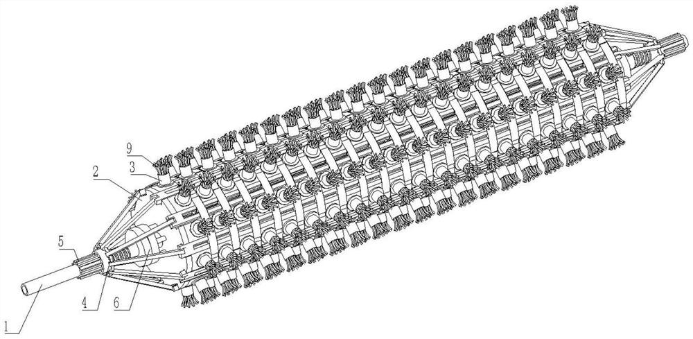
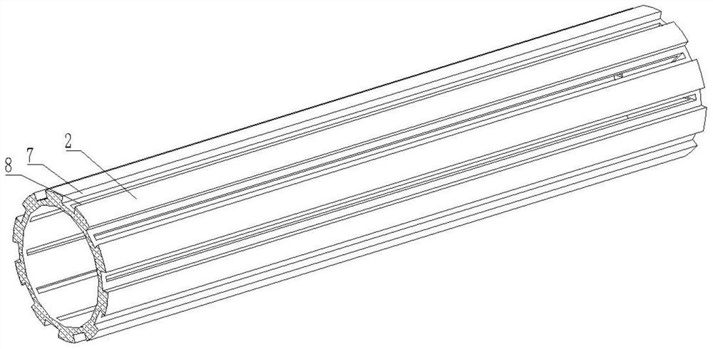
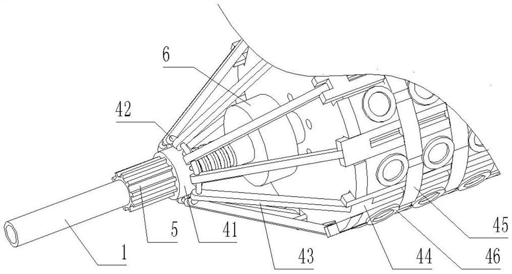
[0031] see Figure 1-6 , a textile fiber cleaning roller, comprising a rotating tube 1, the surface of the rotating tube 1 is provided with a fixing mechanism 5, the surface of the fixing mechanism 5 is provided with a cleaning mechanism 4, the surface of the cleaning mechanism 4 is provided with a roller sleeve 2, the surface of the roller sleeve 2 The surface is fixedly connected with several steel wire columns 3, and the top of the steel wire column 3 is fixedly connected with several cleaning steel wires 9. The surface of the fixing mechanism 5 is provided with a cleaning mechanism 6, and the cleaning mechanism 6 is located on the right side of the cleaning mechanism 4.

[0032] In this embodiment, the surface of the roller sleeve 2 is provided with several long grooves 7, and the interior of the roller sleeve 2 is provided with several water spray grooves 8, and the several long grooves 7 and the water spray grooves 8 are all centered around the center of the roller sleeve...

Embodiment 2

[0042] see Figure 7 , on the basis of Embodiment 1, in this embodiment, the cleaning mechanism 6 includes a water tray 61, and the right side of the water tray 61 is connected with several water pipes 63, and several water pipes 63 are all symmetrical to the center of the water tray 61 The shafts are distributed in a circular array, the surface of the rotating tube 1 is provided with water outlet holes 62, the water outlet holes 62 are located inside the water tray 61, the surface of the water pipe 63 is connected with a connecting pipe 64, and the bottom end of the connecting pipe 64 is fixedly connected with a nozzle 65.

[0043] Inject clean water through the two ends of the rotating tube 1, then enter the inside of the water pipe 63, then enter the inside of the connecting pipe 64 and spray it out from the position of the nozzle 65, and flush the textile fiber cloth with water, making the cleaning process more efficient efficient.

[0044] It is worth mentioning that the i...


PUM

PropertyMeasurementUnit
Thicknessaaaaaaaaaa

Abstract

The invention relates to the technical field of textile, and discloses a textile fiber cleaning roller. The textile fiber cleaning roller comprises a rotating pipe, a fixing mechanism is arranged on the surface of the rotating pipe, a cleaning mechanism is arranged on the surface of the fixing mechanism, a rolling sleeve is arranged on the surface of the cleaning mechanism, a plurality of steel wire columns are fixedly connected to the surface of the rolling sleeve, a plurality of cleaning steel wires are fixedly connected to the tops of the steel wire columns, a washing mechanism is arrangedon the surface of the fixing mechanism, and the washing mechanism is located on the right side of the cleaning mechanism. According to the textile fiber cleaning roller, rotation of a rotating sleeveis controlled, threaded sleeves on the two sides move relatively, a cleaning plate is opened and enlarged under the action of a plurality of connecting strips, fiber filaments left on the rolling sleeve are opened, the cleaning roller is cleaned, so that the cleaning roller cleans textile fibers more effectively, the cleaning quality of the cleaning roller is improved, the service life of the cleaning roller is prolonged, manual cleaning is not needed, and operation is easy, convenient and rapid.

Description

technical field [0001] The invention relates to the technical field of textiles, in particular to a textile fiber cleaning roller. Background technique [0002] The carding machine, which is widely known in industrial textiles, is an important process in the process of processing cotton fibers and chemical fibers in the textile process. The rolls and fiber rolls or facing the incoming cotton layer and fiber layer are opened, carded and cleaned, so that all curled or lumpy cotton becomes basically straight single fiber. [0003] At present, in the use of textile cleaning rollers, after a long period of use, some textile fibers are easily attached to the roller, resulting in poor cleaning effect in the later stage, and it is very cumbersome for employees to clean up. Therefore, a textile fiber cleaning roller is proposed. solve the problems raised above. Contents of the invention [0004] Aiming at the deficiencies of the prior art, the invention provides a textile fiber c...

Claims


Application Information

Patent Timeline
IPC IPC(8): D06G1/00D06B1/02D06B23/30B08B1/00B08B13/00D06B23/02
CPCD06G1/00D06B1/02D06B23/30B08B13/00D06B23/02B08B1/10
Inventor 李兵阚新华
Owner ZHEJIANG MEILAIYA TEXTILE
Learn More