
Anti-corrosion, anti-wear and anti-slagging device of wall type pulverized coal fired boiler

A pulverized coal boiler and anti-corrosion technology, which is applied in the field of anti-corrosion, anti-wear, and anti-slagging devices, can solve problems such as slagging, high-temperature corrosion, etc., and achieve the effects of simple system, increased oxygen content, and reduced total NOx emissions

Pending Publication Date: 2021-02-09
XIAN THERMAL POWER RES INST CO LTD
View PDF0 Cites 0 Cited by
  • Summary
  • Abstract
  • Description
  • Claims
  • Application Information

AI Technical Summary

Problems solved by technology

[0004] After adopting SOFA technology, the gas-solid two-phase flow combustion process at the burner nozzle adjacent to both sides of the wall belongs to anoxic combustion, so that the water-cooled walls of both sides of the wall are in a reducing atmosphere, which is prone to high-temperature corrosion or slagging

Method used


Image

  • Anti-corrosion, anti-wear and anti-slagging device of wall type pulverized coal fired boiler
  • Anti-corrosion, anti-wear and anti-slagging device of wall type pulverized coal fired boiler

Examples


Embodiment 1

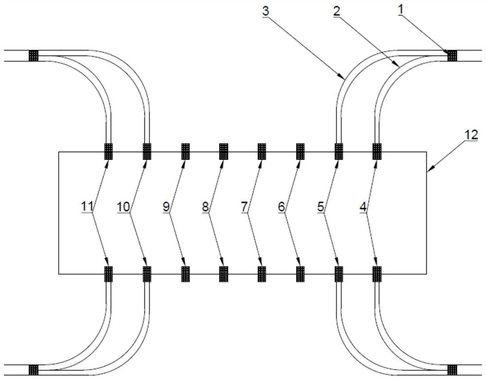
[0028] see figure 1 , is an improved schematic diagram of the corresponding pulverized coal pipelines of the burners adjacent to the two side walls in the first layer of burners. The rich-lean separation device 1 used in this embodiment is a fixed thick-lean separation device. The layers are exactly the same. When put into operation, the pulverized coal pipeline at its outlet is divided into a light phase pulverized coal pipeline 2 and a dense phase pulverized coal pipeline 3 through the separation of the fixed thick-lean separation device 1. The first burner 4 is connected with the eighth burner 11 so that its pulverized coal amount is less than the average value of the pulverized coal amount of the layer, and the dense phase pulverized coal pipeline 3 is connected with the second burner 5 and the seventh burner 10, Therefore, under the condition that the air intake of the original burner is constant, the combustion process of the pulverized coal airflow of the first burner ...

Embodiment 2

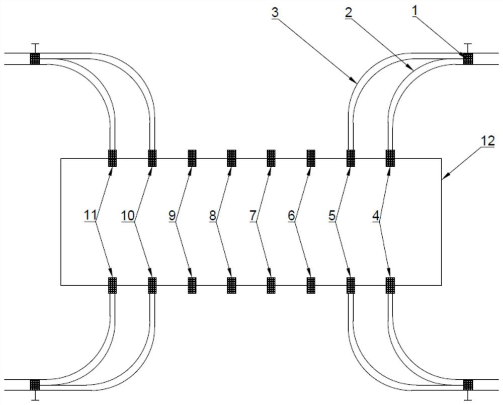
[0030] see figure 2 , this embodiment is an improved schematic diagram of the corresponding pulverized coal pipelines of the burners adjacent to the two side walls in the first layer of burners. In this embodiment, the thick-thin separation device 1 is an adjustable thick-thin separation device. The layer is exactly the same. When put into operation, the pulverized coal pipeline at the outlet is divided into a light-phase pulverized-coal pipeline 2 and a dense-phase pulverized-coal pipeline 3 through the separation function of the adjustable thick-lean separation device, and the pulverized coal pipeline can be adjusted. The light phase pulverized coal pipeline 2 is connected with the first burner 4 and the eighth burner 11 adjacent to the two side walls, so that the amount of pulverized coal is less than the average value of the pulverized coal quantity of this layer, and the pulverized coal pipeline 3 of the dense phase is connected with the second burner 11. The burner 5 i...


PUM


Abstract

The invention discloses an anti-corrosion, anti-wear and anti-slagging device of a wall type pulverized coal fired boiler. The device comprises dense-thin separation devices, the dense-thin separationdevices are arranged on pulverized coal pipelines connected with combustors adjacent to two side walls, an outlet of each dense-thin separation device is divided into two paths, one path is a thin-phase pulverized coal pipeline, the other path is a dense-phase pulverized coal pipeline, and the thin-phase pulverized coal pipelines and the dense-phase pulverized coal pipelines are connected with the combustors adjacent to the two side walls. According to the device, the combustion process of pulverized coal airflow of the combustors adjacent to the two side walls can be under an oxygen-enrichedcombustion condition, and therefore erosive wear and the slagging degree of combustion particles and coal ash particles to the water cooling wall can be effectively reduced; and meanwhile, the wall face atmosphere is effectively changed, the temperature level of combustion products of eroding the water cooling wall is reduced, and the high-temperature corrosion degree and the slagging degree in the boiler are solved or relieved.

Description

technical field [0001] The invention is used in a combustion system of a pulverized coal boiler, and in particular relates to an anti-corrosion, anti-wear and anti-slagging device for a wall-type combustion pulverized coal boiler. Background technique [0002] At present, the low NOx combustion technology adopted by boilers is mainly based on SOFA technology, that is, each burner performs anoxic combustion, and the entire burner area is in a reducing atmosphere. For wall-fired pulverized coal boilers, this will significantly increase the high-temperature corrosion of the water-cooled walls on both sides of the wall; when the tendency of coal-fired slagging is strong, it will also increase the degree of slagging on both sides of the wall. [0003] For the 1000MW wall-type pulverized coal boiler, the burners are arranged on the front and rear walls oppositely, each wall has 3 layers of burners, and each layer has 8 burners. Among them, the outermost burner is close to the two...

Claims


Application Information

Patent Timeline
IPC IPC(8): F23C6/04F23M5/08F23J3/00
CPCF23C6/04F23J3/00F23M5/08Y02E20/34
Inventor 王春昌党黎军沈植
Owner XIAN THERMAL POWER RES INST CO LTD
Learn More