
Silicon-based polarization beam splitting rotator based on adiabatic cone asymmetric coupling and Y branch

An asymmetric coupling and polarization beam splitting technology, which is applied in the direction of instruments, light guides, optics, etc., can solve the problems of small device manufacturing tolerance, poor polarization separation, and low polarization extinction ratio, and achieve a large working wavelength range and large production Effect of Tolerance, High Extinction Ratio

Active Publication Date: 2021-02-05
SOUTHWEST JIAOTONG UNIV
View PDF8 Cites 8 Cited by
  • Summary
  • Abstract
  • Description
  • Claims
  • Application Information

AI Technical Summary

Problems solved by technology

Most of the above papers are single-stage coupling or multi-stage asymmetric coupling. However, although the asymmetric coupling structure is simple in structure, it is very sensitive to the waveguide width and coupling length, which makes the manufacturing tolerance of the device extremely small. For example, J.Wang et al. designed Ridge waveguide multi-stage asymmetric coupling polarization beam splitting rotator, the manufacturing tolerance of the waveguide thickness is less than 5nm, so it is difficult to meet the requirements of the current technology (J.Wang, B.Niu, Z.Sheng, A. Wu, X.Wang, S.Zou, M.Qi, and F.Gan,"Design of a SiO2top-cladding and compact polarization splitter-rotator based on a ribdirectional coupler,"Opt.Express 22, 4137(2014)), Although the adiabatic tapered structure can be used to increase the manufacturing tolerance, the ordinary adiabatic tapered structure can only be improved to a limited extent, and the second-etched adiabatic tapered structure has a large manufacturing tolerance, such as the tapered one designed by Y Xiong et al. Etching asymmetrically coupled polarization beam splitters has a manufacturing tolerance of 50nm, but multi-layer etching creates new requirements for the manufacturing process and increases the difficulty of manufacturing (Y.Xiong, D.X.Xu, J.H.Schmid, P.Cheben , S.Janz, and W.N.Ye,"Fabrication tolerant and broadband polarizationsplitter and rotator based on a taper-etched directional coupler,"Opt.Express22, 17458(2014))
Polarization beam splitting rotators with Y-branch structure usually have a large manufacturing tolerance. However, due to the inherent shortcomings of the structure, such as poor polarization separation, the polarization processing device based on this structure usually has a low polarization extinction ratio.
[0004] According to the above analysis, it can be seen that the current silicon-based optical waveguide polarization beam splitting rotator is difficult to achieve a balance in the two indicators of polarization extinction ratio and manufacturing tolerance, and these two indicators are important indicators to measure the performance and practicability of polarization processing. directly affect the actual application value of the device

Method used


Image

  • Silicon-based polarization beam splitting rotator based on adiabatic cone asymmetric coupling and Y branch
  • Silicon-based polarization beam splitting rotator based on adiabatic cone asymmetric coupling and Y branch
  • Silicon-based polarization beam splitting rotator based on adiabatic cone asymmetric coupling and Y branch

Examples


Embodiment Construction

[0029] The present invention will be described in further detail below in conjunction with the accompanying drawings and specific implementation methods.

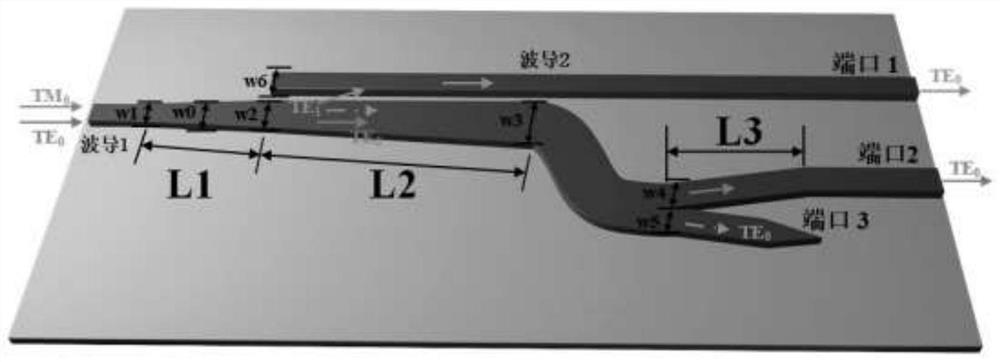
[0030] Silicon-based polarization beam splitting rotator based on adiabatic tapered asymmetric coupling and Y branch of the present invention such as figure 1 As shown, silicon dioxide is used as the substrate and the cladding layer; a buffer layer of silicon material is added between the substrate and the cladding layer, and a ridge waveguide is constructed on the buffer layer to form the main body of the polarization beam splitter rotator.

[0031] The above-mentioned ridge waveguide consists of three sections:

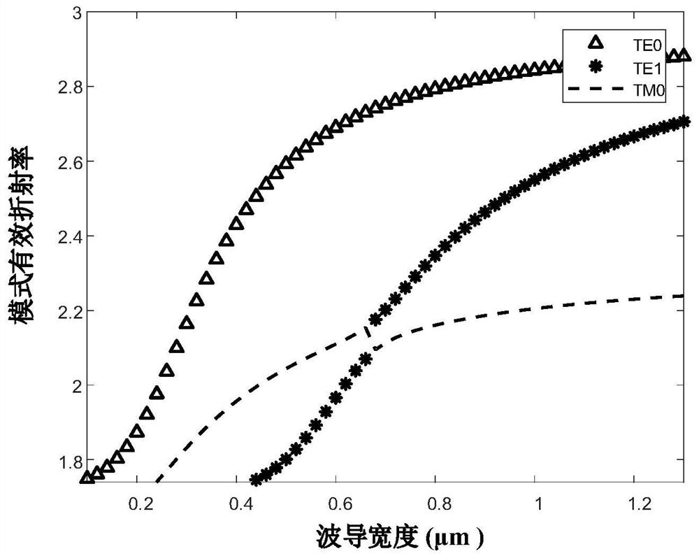
[0032] The first section is an adiabatic conical structure with a width from W 1 fade to W 2 , after the polarization mode conversion critical width W in the gradient process 0 , implementing TM inside the waveguide 1 0 polarization mode to TE 1 Conversion of polarization modes.

[0033] The second section ...


PUM


Abstract

The invention discloses a silicon-based polarization beam splitting rotator based on adiabatic cone asymmetric coupling and a Y branch. According to the rotator, silicon dioxide is adopted as a substrate and a coating layer; a buffer layer made of a silicon material is additionally arranged between the substrate and the coating layer, and a ridge waveguide is constructed on the buffer layer, and therefore, a polarization beam splitting rotator main body can be formed. The ridge waveguide is composed of three sections of structures. The first section is of a heat insulation conical structure, the width of the first section gradually changes from W1 to W2, and conversion from a TM0 polarization mode to a TE1 polarization mode is achieved in a waveguide 1; the second section adopts an asymmetric coupling structure and a heat insulation conical structure to realize polarization beam splitting and rotation from a waveguide 1 to a waveguide 2; and the third section consists of a Y branch andis connected with the second section through an S-shaped bent structure to realize second-stage polarization beam splitting and rotation. The silicon-based optical polarization beam splitting rotatorhas the advantages of large working wavelength range, high extinction ratio, low loss and the like, and has important application in systems of optical communication, photoelectric signal processingand the like.

Description

technical field [0001] The invention belongs to the fields of silicon-based photon integration, multi-dimensional multiplexing of optical signals, polarization mode conversion, etc., and in particular relates to a silicon-based polarization beam splitting rotator based on adiabatic tapered asymmetric coupling and Y branch. Background technique [0002] The silicon-based optical waveguide polarization processor device is an integrated polarization processing device based on the polarization characteristics of silicon materials. The polarization of light mainly includes two polarization modes: TE (transverse electric mode) and TM (transverse magnetic mode) in silicon-based optical waveguides. The practical application mainly focuses on the fundamental mode of these two polarization modes, namely TE 0 and TM 0 polarization mode (or quasi-TE 0 Polarization modes and quasi-TM 0 polarization mode). Polarization beam splitting mainly adopts the principle of phase matching, and ...

Claims


Application Information

Patent Timeline
Patent Type & Authority Applications(China)
IPC IPC(8): G02B6/126G02B6/125
CPCG02B6/125G02B6/126G02B2006/12038G02B2006/12085
Inventor 解长健邹喜华李沛轩潘炜闫连山
Owner SOUTHWEST JIAOTONG UNIV
Learn More