
Annular cooler and water tank dredging device thereof

A technology of dredging device and ring cooler, which is applied in the field of metallurgy to achieve the effect of simple design and easy application

Pending Publication Date: 2021-02-05
HUNAN ZHONGZHI CHANGTIAN HEAVY IND TECH
View PDF0 Cites 0 Cited by
  • Summary
  • Abstract
  • Description
  • Claims
  • Application Information

AI Technical Summary

Problems solved by technology

[0006] The main purpose of the present invention is to provide an annular cooler and its water tank dredging device. The present invention aims to solve the technical problem of cleaning the ash in the water tank during the operation of the annular cooler

Method used


Image

  • Annular cooler and water tank dredging device thereof
  • Annular cooler and water tank dredging device thereof
  • Annular cooler and water tank dredging device thereof

Examples


Embodiment Construction

[0033] It should be understood that the specific embodiments described here are only used to explain the present invention, not to limit the present invention.

[0034] The following will clearly and completely describe the technical solutions in the embodiments of the present invention with reference to the accompanying drawings in the embodiments of the present invention. Obviously, the described embodiments are only part of the embodiments of the present invention, not all of them. Based on the embodiments of the present invention, all other embodiments obtained by persons of ordinary skill in the art without creative efforts fall within the protection scope of the present invention.

[0035] It should be noted that all directional indications (such as up, down, left, right, front, back...) in the embodiments of the present invention are only used to explain the relationship between the components in a certain posture (as shown in the accompanying drawings). Relative positi...


PUM


Abstract

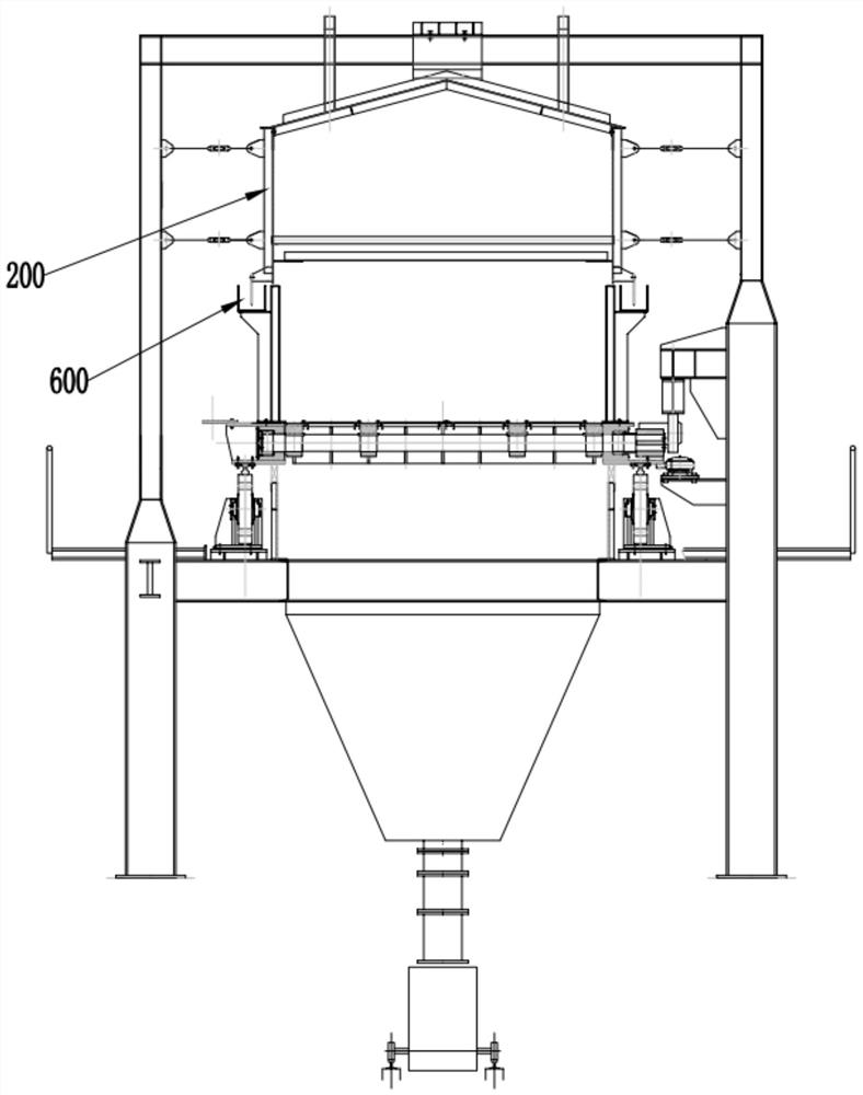
The invention provides a water tank dredging device of an annular cooler. The water tank dredging device of the annular cooler comprises a support connected with the annular cooler and a dredging module fixed to the support. The dredging module comprises a hollow conveying cylinder and a plurality of material digging hoppers; a rotating shaft is arranged in the conveying cylinder; a first end of the rotating shaft is connected with a motor so as to be driven by the motor to rotate; a discharging opening is formed in the side wall, close to the first end, of the conveying cylinder; the openingdirection of the discharging opening is downward; the material digging hoppers are fixed to the rotating shaft and rotate along with the rotating shaft; the material digging hoppers extend into a water tank of the annular cooler; openings of the material digging hoppers face the rotating direction of the rotating shaft; a plurality of feeding ports are further formed in the side wall of the conveying cylinder; the feeding ports and the material digging hoppers are correspondingly arranged; and the material digging hoppers penetrate through the feeding ports and are connected with the rotatingshaft. The water tank dredging device of the annular cooler aims to solve the technical problem of cleaning accumulated dust in the water tank in the operation process of the annular cooler.

Description

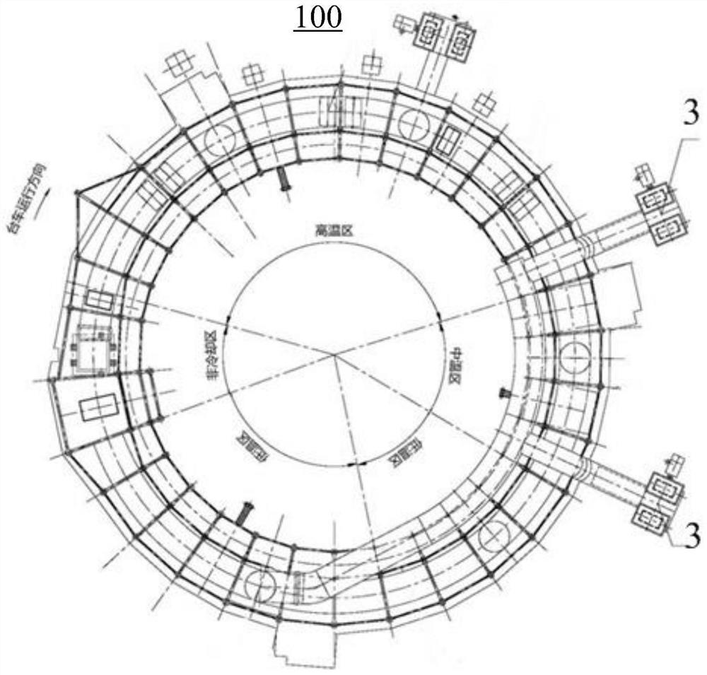
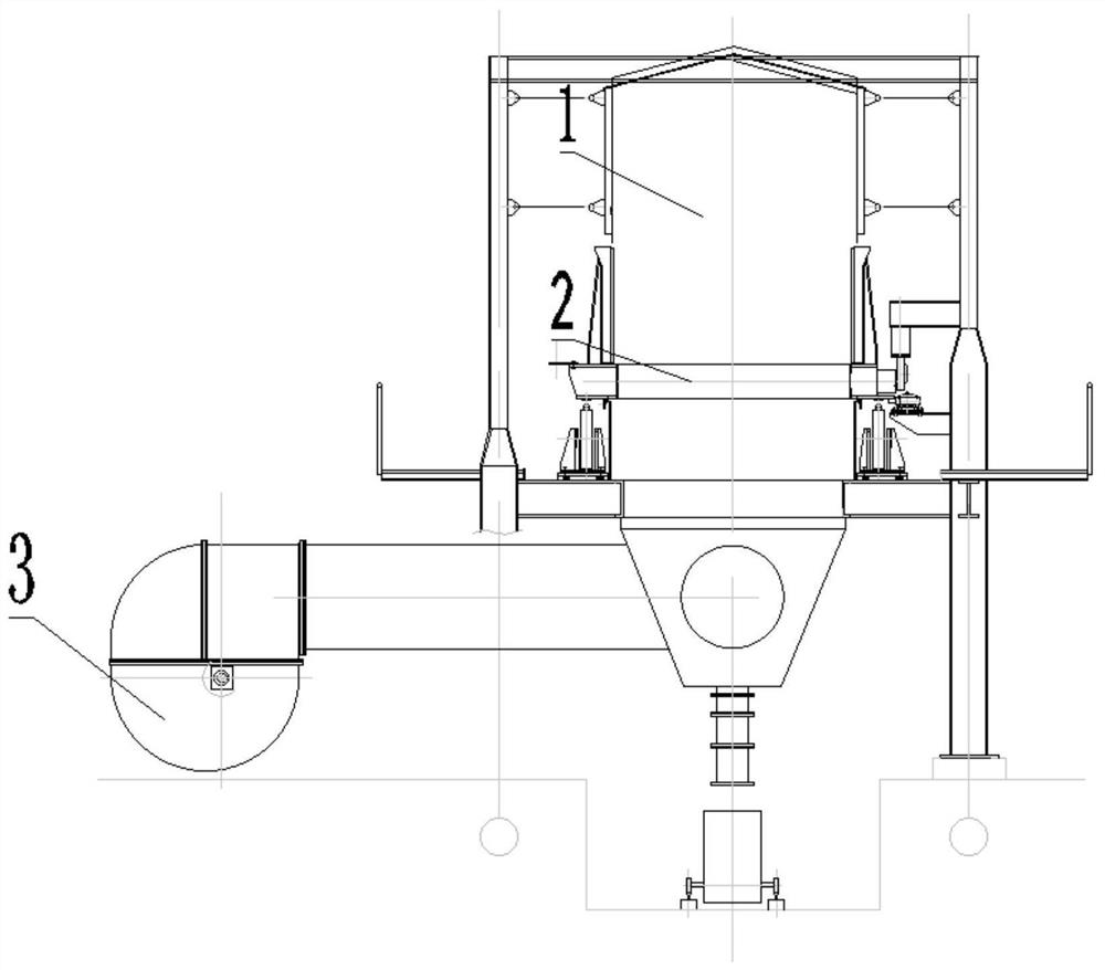
technical field [0001] The invention relates to the technical field of metallurgy, in particular to an annular cooler and a water tank dredging device thereof. Background technique [0002] In the production of the metallurgical industry, the ring cooler is an important process equipment in the upstream process of smelting. Its main function is to cool the high-temperature sintered ore roasted by the sintering machine. [0003] Please refer to Figure 1-2 , is a structural schematic diagram of an annular cooler 100 in the prior art. The annular cooler 100 is in the shape of a ring as a whole, and the sintered material runs in the annular cooler 100 for one cycle through the trolley 1 to complete cooling and unloading. specific, figure 2 It is a radial (direction to the center of the annular cooler) sectional view of the annular cooler 1. The sintered material (such as sintered ore) is arranged on the grate plate 2 of the trolley 1, and the trolley 1 surrounds the center o...

Claims


Application Information

Patent Timeline
IPC IPC(8): F27D25/00F27D15/02
CPCF27D15/02F27D25/00
Inventor 李岩何晴宁江波申理仁肖跃军
Owner HUNAN ZHONGZHI CHANGTIAN HEAVY IND TECH
Learn More