
Tin soldering device with pin protection function for electronic part assembling

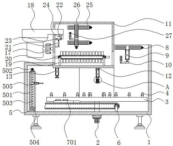
A technology for electronic components and protection functions, which is applied in the field of soldering devices with pin protection functions for electronic component assembly, which can solve problems such as waste, pin angle changes, and unusable parts, so as to reduce shock transmission and increase Accuracy, the effect of preventing collision damage or deformation

Inactive Publication Date: 2021-02-05
东莞市帕特慕可科技有限公司
View PDF0 Cites 4 Cited by
  • Summary
  • Abstract
  • Description
  • Claims
  • Application Information

AI Technical Summary

Problems solved by technology

[0004] The purpose of the present invention is to provide a soldering device with a pin protection function for assembling electronic components, so as to solve the problem that the existing soldering devices proposed in the background art are prone to lead to problems when transporting some parts on the electronic components. Parts are bumped or other problems cause the angle of the pins on these parts to change or be damaged, resulting in the fact that the part cannot be installed on the electronic component or the part cannot be used to cause waste.

Method used


Image

  • Tin soldering device with pin protection function for electronic part assembling
  • Tin soldering device with pin protection function for electronic part assembling
  • Tin soldering device with pin protection function for electronic part assembling

Examples


Embodiment Construction

[0027] The following will clearly and completely describe the technical solutions in the embodiments of the present invention with reference to the accompanying drawings in the embodiments of the present invention. Obviously, the described embodiments are only some, not all, embodiments of the present invention.

[0028] In the description of the present invention, unless otherwise stated, the meaning of "plurality" is two or more; the terms "upper", "lower", "left", "right", "inner", "outer" , "front end", "rear end", "head", "tail", etc. indicate the orientation or positional relationship based on the orientation or positional relationship shown in the drawings, and are only for the convenience of describing the present invention and simplifying the description, rather than indicates or implies that the device or element referred to must have a particular orientation, be constructed and operate in a particular orientation, and therefore should not be construed as limiting the...


PUM


Abstract

The invention relates to a tin soldering device with a pin protection function for electronic part assembling. The tin soldering device comprises an equipment shell and a second belt conveyor, whereina first motor is installed at the lower end of the equipment shell, a rotating platform is arranged in the middle of the lower wall of the interior of the equipment shell, a positioning support is fixed to the rotating platform, a pin shearing mechanism and a first belt conveyor are sequentially arranged on the lower wall of the interior of the equipment shell anticlockwise, an electronic part body is placed at the upper end of the equipment shell, a first electric sliding rail is arranged on the rear wall of the equipment shell, and a second multi-section hydraulic cylinder is installed at the lower end of the first electric sliding rail. The tin soldering device with the pin protection function for electronic part assembling has the beneficial effects that pins of capacitors are inserted into pin protection sleeves to be protected, so that the situation of waste caused by the fact that the pins are bent or damaged due to collision and other problems in the conveying process and thecapacitors cannot be used consequently is prevented.

Description

technical field [0001] The invention relates to the technical field of electronic component assembly, in particular to a soldering device with pin protection function for electronic component assembly. Background technique [0002] Electronic components are some components that make up electronic equipment. Electronic components need to be processed and assembled to form a whole before they are assembled into electronic equipment. Usually, soldering devices are an important equipment in the assembly of electronic components. [0003] When the existing soldering device is transporting some parts on the electronic parts, it is easy to cause the parts to be bumped or other problems to change or damage the angle of the pins on these parts, so that the parts cannot be installed on the electronic parts or roughly This part cannot be used to cause the problem of waste. Contents of the invention [0004] The purpose of the present invention is to provide a soldering device with a...

Claims


Application Information

Patent Timeline
Patent Type & Authority Applications(China)
IPC IPC(8): B23K3/08B23K101/36
CPCB23K3/08B23K2101/36
Inventor 陈海华钟海瑜
Owner 东莞市帕特慕可科技有限公司
Learn More