Preparation method of split gate MOSFET device and split gate MOSFET device

A split gate and device technology, which is applied in semiconductor/solid-state device manufacturing, semiconductor devices, electrical components, etc., can solve the problems of unsatisfactory demand and fixed resistivity of split gate MOSFET

Pending Publication Date: 2021-01-29
SHANGHAI CHANGYUAN WAYON MICROELECTRONICS
View PDF3 Cites 0 Cited by
  • Summary
  • Abstract
  • Description
  • Claims
  • Application Information

AI Technical Summary

Problems solved by technology

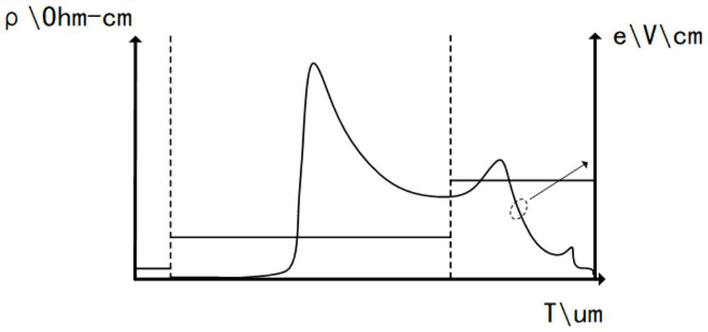
However, whether it is a single-layer split-gate MOSFET or a double-layer split-gate MOSFET, its resistivity is constant, which cannot meet the needs of practical applications.
Therefore, it has become a difficult problem for those skilled in the art to solve the problem that the above-mentioned split-gate MOSFET has a constant resistivity and cannot meet the needs of practical applications.

Method used


Image

  • Preparation method of split gate MOSFET device and split gate MOSFET device
  • Preparation method of split gate MOSFET device and split gate MOSFET device
  • Preparation method of split gate MOSFET device and split gate MOSFET device

Examples


Embodiment Construction

[0069] The following will clearly and completely describe the technical solutions in the embodiments of the present invention with reference to the accompanying drawings in the embodiments of the present invention. Obviously, the described embodiments are only some, not all, embodiments of the present invention. Based on the embodiments of the present invention, all other embodiments obtained by persons of ordinary skill in the art without creative efforts fall within the protection scope of the present invention.

[0070] It should be noted that, in the case of no conflict, the embodiments of the present invention and the features in the embodiments can be combined with each other.

[0071] The present invention will be further described below in conjunction with the accompanying drawings and specific embodiments, but not as a limitation of the present invention.

[0072] The invention provides a method for preparing a split gate MOSFET device, wherein, in combination with ...


PUM


Abstract

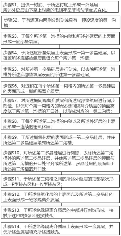
The invention relates to the technical field of semiconductors, in particular to a preparation method of a split gate MOSFET device and the split gate MOSFET device. The method comprises the steps of:S1, providing a substrate, forming an epitaxial layer on the substrate, and enabling the width of the bottom surface of the epitaxial layer to be equal to the width of the top surface of the substrate; wherein the corresponding resistivity of the epitaxial layer is changed in a non-uniform gradual change manner from bottom to top. The preparation method has the beneficial effects that: the epitaxial layer is formed on the substrate, and the corresponding resistivity of the epitaxial layer from bottom to top is changed in a non-uniform gradual change manner, so that the internal electric fielddistribution of the device is optimized, the coverage area of two-dimensional breakdown electric field lines at the same position of the device with the same size is larger, and while the electric field intensity is improved, the intensity of the electric field close to the substrate direction is obviously increased, and a depletion region is broadened downwards, so that the breakdown voltage isimproved, and the on-resistance and the static loss of the device are reduced under the same target voltage.

Description

technical field [0001] The invention relates to the technical field of semiconductors, in particular to a method for preparing a split-gate MOSFET device and the split-gate MOSFET device. Background technique [0002] The split gate MOSFET (Metal-Oxide-Semiconductor Field-Effect Transistor metal-oxide semiconductor field effect transistor) power device is an improved trench power MOSFET based on the traditional trench U-MOSFET, and its switching speed Faster, lower switching losses, and better device performance. [0003] The traditional trench U-MOSFET has only one layer of polysilicon in the deep trench, while the split gate MOSFET adopts a charge-coupled structure, that is, the deep trench of the split gate MOSFET has two layers of polysilicon, the upper polysilicon is the gate polysilicon, and the lower polysilicon For the source polysilicon, on the one hand, the split gate acts as a polycrystalline field plate in the body to assist in depleting the drift region, thereb...

Claims


Application Information

Patent Timeline
Patent Type & Authority Applications(China)
IPC IPC(8): H01L29/06H01L29/786H01L21/336
CPCH01L29/66742H01L29/0615H01L29/78606
Inventor 马一洁苏亚兵
Owner SHANGHAI CHANGYUAN WAYON MICROELECTRONICS
Why Eureka
Try Eureka