Excavator bucket for engineering construction

A technology for engineering construction and excavators, which is applied to mechanically driven excavators/dredgers, earth movers/shovels, construction, etc., which can solve the problems of failure to achieve better excavation performance, heavy buckets, and high labor costs. question

Pending Publication Date: 2021-01-29
黄付银
View PDF0 Cites 0 Cited by
  • Summary
  • Abstract
  • Description
  • Claims
  • Application Information

AI Technical Summary

Problems solved by technology

Therefore, excavators usually need to be equipped with multiple spare buckets with different bucket capacities to meet the needs of different working conditions in engineering construction. This greatly increases the cost input. On the other hand, the bucket is usually heavy and inconvenient to transport and carry. In particular, the disassembly operation during replacement is usually done manually, which is time-consuming and laborious, and the labor cost is high. In addition, on the other hand, the bucket Bucket capacity specifications change in steps, and it is usually difficult to adjust the bucket capacity to the optimum value by replacing the bucket
[0003] At the same time, during the continuous operation of the excavator, the density of the material sometimes changes greatly with the progress of the operation. large, and the density difference between the upper and lower soils is relatively significant. In this case, changing buckets with different bucket capacities according to the actual situation is obviously conducive to improving operating efficiency and ensuring the working stability of the equipment, but it is limited by the replacement of existing buckets. It is difficult, coupled with unfavorable conditions such as terrain, it is generally not easy to replace the bucket, but to use the same bucket for continuous operation, which is obviously not scientific and reasonable
[0004] It is undeniable that among the bucket designs recorded in the existing literature, there are also plans to design the bucket capacity as an adjustable type, but the adjustment structure based on it is not scientific, the stability is usually poor, and the adjustment is not convenient and quick enough, especially The parameters such as shape, curve and size adopted are quite different from those of existing buckets, and cannot meet the bucket processing parameter requirements accumulated over a long period of time, and fail to achieve better excavation performance. failed to be implemented

Method used


Image

  • Excavator bucket for engineering construction
  • Excavator bucket for engineering construction
  • Excavator bucket for engineering construction

Examples


Embodiment 1

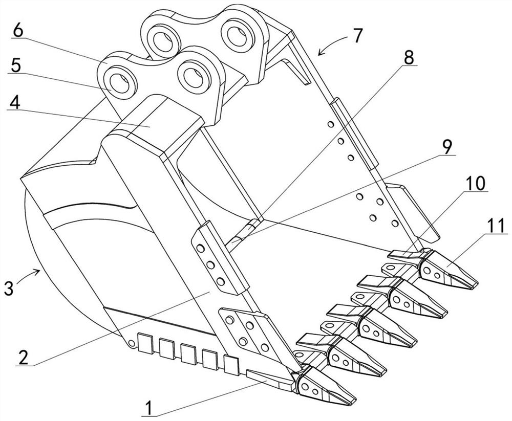
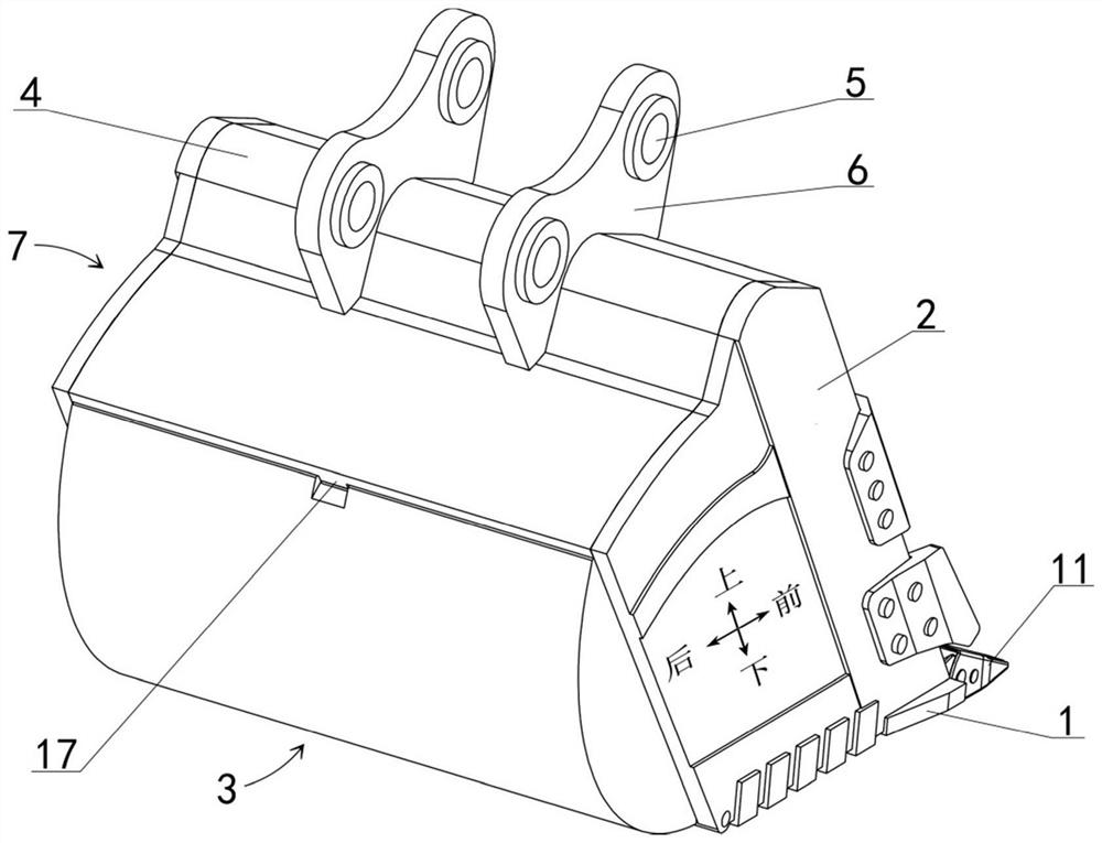
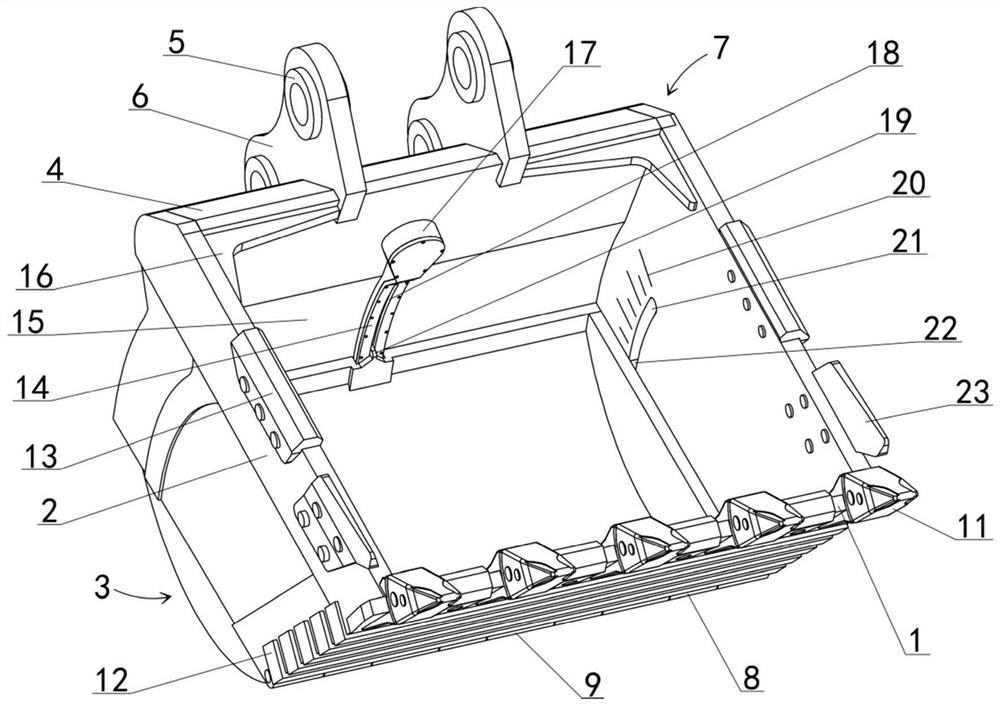
[0025] see Figure 1-5 As shown, the engineering construction excavator bucket disclosed in this embodiment includes a bucket body 7 and a bottom cover 3 arranged at the rear of the bucket body 7; the bucket body 7 has an inner cavity, and the bucket body 7 The rear end is open and is in the shape of a transparent frame. The lower part of the front end of the bucket body 7 is fixed with a tooth seat plate 1, also known as a knife plate. The left and right sides of the bucket body 7 are fixed with side plates 2, also known as side knife plates. 7. The back plate 4 and the ear plate 6 are fixed on the upper side. The rear lower end of the bucket body 7 is provided with a first hinged part 9. The middle rear part of the inner side of the upper wall of the bucket body 7 is arc-shaped, which is called an arc surface 15. The geometric central axes of the arc-shaped surface 15 and the first hinge part 9 coincide and extend along the left and right directions. Bucket teeth 11, the ba...

Embodiment 2

[0047] see image 3 , 8 As shown, in the excavator bucket for engineering construction disclosed in Embodiment 1, a guide groove 18 is opened on the lower side of the part of the rope box 17 located at the arc surface 15, so that the traction part 19 can move with the traction rope 24, usually In other words, when implementing this embodiment, the width of the guide groove 18 is minimized to ensure that the materials in the bucket body 7 will not easily enter the rope box 17 through the guide groove 18 during the operation of the excavator; , when implementing this bucket, a corresponding leak hole can also be opened at the rear end of the rope box 17, so that the materials entering the rope box 17 can be discharged, and the materials in the rope box 17 can be prevented from causing adverse effects on the adjustment function of the bucket capacity. In addition, in order to better solve the above-mentioned problems, the present embodiment carries out the following improvements...


PUM


Abstract

The invention relates to an excavator component, and particularly discloses an excavator bucket for engineering construction. The excavator bucket for engineering construction comprises a frame-shapedbucket body, a rope box is fixedly arranged in the bucket body, a rope wheel and a traction rope are arranged in the rope box, a bottom cover is rotatably and fixedly arranged at the rear end of thebucket body, a traction part is arranged at the upper end of the bottom cover, the traction part is connected with the traction rope, the bottom cover rotates forwards, the bucket capacity is reduced,otherwise, the bucket capacity is increased, a wheel shaft of the rope wheel is connected with a worm wheel, a worm which meshes with the worm wheel and a motor device which drives the worm to rotateare arranged in an inner cavity of a back plate, and bucket capacity adjustment can be achieved when the motor device drives the worm to rotate. The excavator bucket has the bucket capacity adjustingfunction, adjusting can be carried out according to actual working conditions, the operation efficiency can be improved to the maximum extent on the premise that stable work of a excavator is guaranteed; the adjusting operation of the bucket capacity is convenient and fast, time-saving and labor-saving; and a spare bucket is not required to be arranged, so that the equipment acquisition cost is reduced, and the defects of labor consumption, operation efficiency reduction and the like of the spare bucket in transportation, disassembly and assembly are overcome.

Description

technical field [0001] The invention relates to an accessory of engineering machinery, in particular to an excavator bucket for engineering construction. Background technique [0002] The bucket is an important component of the excavator, and its capacity is one of the three most important parameters of the excavator (operating weight, engine power and bucket capacity). The bucket capacity of the original bucket is usually the standard bucket volume, which cannot adapt to all working conditions. For example, for light materials with low density, a bucket with a large bucket volume should be selected to reduce power consumption and improve work efficiency. For heavy materials with high density, a bucket with a small bucket capacity should be selected to avoid overloading the excavator and ensure its working stability. Therefore, excavators usually need to be equipped with multiple spare buckets with different bucket capacities to meet the needs of different working condition...

Claims


Application Information

Patent Timeline
IPC IPC(8): E02F3/40
CPCE02F3/40E02F3/401E02F3/404
Inventor 黄付银
Owner 黄付银
Why Eureka
Try Eureka