Pavement robot path planning method

A path planning, robot technology, applied in instruments, two-dimensional position/channel control, vehicle position/route/height control, etc., can solve the problem of not being able to take into account the requirements of U-turn area and comprehensive detection at the same time, high road width restrictions, etc. , to achieve the effect of taking into account the U-turn area and comprehensive detection, high practical value and promotion value, and clear logic

Pending Publication Date: 2021-01-26
成都圭目机器人有限公司
View PDF0 Cites 2 Cited by
  • Summary
  • Abstract
  • Description
  • Claims
  • Application Information

AI Technical Summary

Problems solved by technology

At present, the pavement robot in the prior art adopts a U-turn mode in the form of a spherical bulb bulb, such as figure 1 As shown, it has a high limit on the width of the road surface, and it cannot take into account the requirements of the U-turn area and comprehensive inspection at the same time.

Method used


Image

  • Pavement robot path planning method
  • Pavement robot path planning method
  • Pavement robot path planning method

Examples


Embodiment

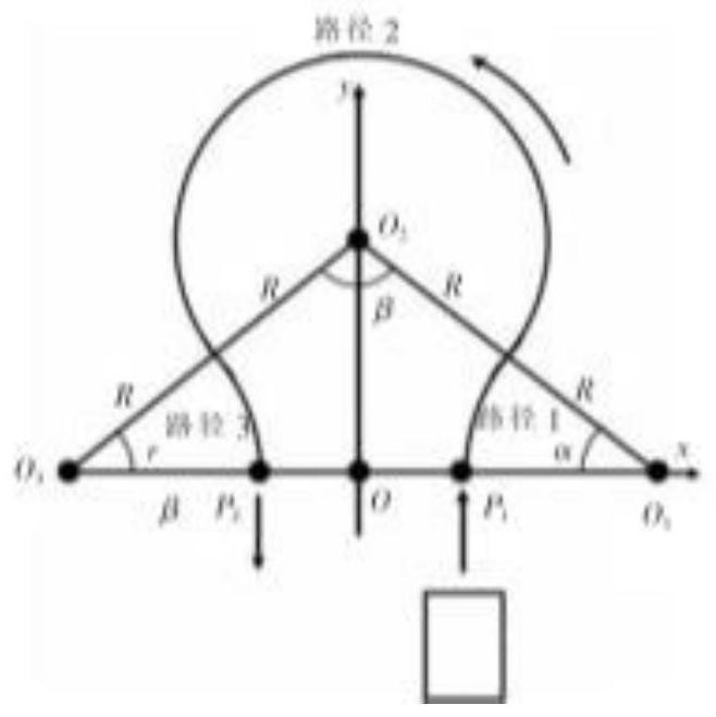
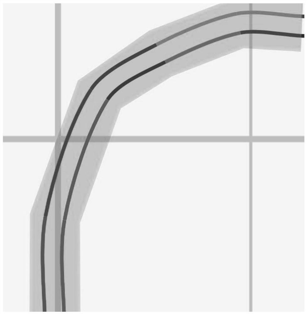
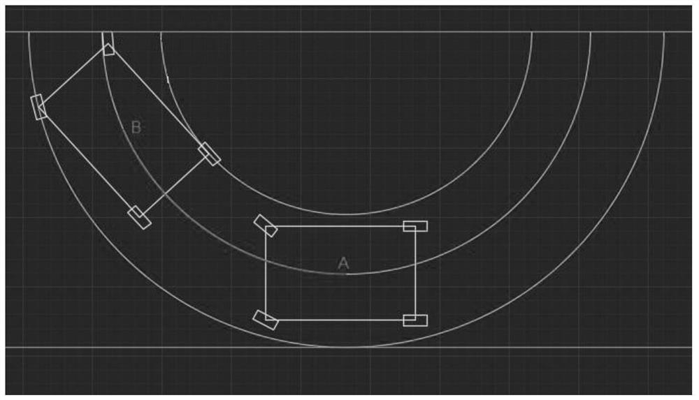
[0036] Such as Figure 2 to Figure 8 As shown, this embodiment provides a road surface robot path planning method and system, the road surface robot is provided with: used to filter the continuous high-density point set generated by the GPS sensor and convert it into a low-density point set containing valid information The point set information filtering module of the set is used to receive planning task information, and the task receiving module of planning start point and end point information is used to record the length, width, wheelbase, wheelbase and center position of the road surface robot, and according to the road surface robot The body posture of the vehicle body is used to obtain the coordinates of any intersection point, the vehicle body information module is used to store the polyline set of road edge information, and the point set information is output according to the recursive algorithm to generate the Besser for planning. Trajectory generation module for Curv...


PUM


Abstract

The invention discloses a pavement robot path planning method. The method comprises the following steps: acquiring a discrete coordinate point set in a walking path of a pavement robot; connecting discrete coordinate points by adopting a Bezier curve algorithm to obtain a smooth curve set; performing left-right equidistant offset according to the widths of the left and right sides of the road andthe measurement width of the pavement robot to obtain a plurality of Bezier curve sets; according to the length, the width, the wheelbase, the wheel track and the center position of the pavement robot, obtaining the center turning radius, the inner side turning radius and the outer side turning radius of the pavement robot; taking the tail end of a Bezier curve of a walking path of the pavement robot as a starting point, and solving an intersection point of the turning vehicle body contour and a road edge line; taking the intersection point of the turning vehicle body outline of the pavement robot and the road edge line as the starting point, solving the intersection point of the outer turning curve and the lane edge, and repeating the advancing and retreating operations until the advancing direction of the pavement robot coincides with the adjacent Bezier curve.

Description

technical field [0001] The invention relates to the technical field of road surface robots, in particular to a path planning method for a road surface robot. Background technique [0002] When the pavement robot performs road appearance and 3D non-destructive damage control, it needs to perform multiple coverage measurements on the road surface. The path is mainly composed of a walking path and a U-turn path. At present, the pavement robot in the prior art adopts a U-turn mode in the form of a spherical bulb bulb, such as figure 1 As shown, it has a high limit on the road width, and it cannot take into account the requirements of the U-turn area and comprehensive inspection at the same time. [0003] Therefore, it is urgent to propose a road surface robot path planning method with clear logic, comprehensive detection coverage, and reliable U-turn. Contents of the invention [0004] For the problems referred to above, the object of the present invention is to provide a ro...

Claims


Application Information

Patent Timeline
Patent Type & Authority Applications(China)
IPC IPC(8): G05D1/02
CPCG05D1/0088G05D1/0212G05D1/0278
Inventor 陈茂林肖唐杰王宇琛邓勇军杨辉桂仲成
Owner 成都圭目机器人有限公司
Why Eureka
Try Eureka