Eureka AIR delivers breakthrough ideas for toughest innovation challenges, trusted by R&D personnel around the world.

Self-locking flange pair and flexible connecting pipe

A flexible joint and self-locking technology, applied in the direction of pipes/pipe joints/fittings, hoses, pipes, etc., can solve the problems of less winding space, poor resistance to pull-out, etc., to achieve good integrity and eliminate concentrated stress , Improve the effect of the application range

Inactive Publication Date: 2021-01-19
湖北维普路船舶机电科技有限公司
View PDF5 Cites 2 Cited by
  • Summary
  • Abstract
  • Description
  • Claims
  • Application Information

AI Technical Summary

Problems solved by technology

Although this patent has simple structure, good integrity, small size, and light weight, the end of the skeleton layer of the elastomer is turned outward along the top surface of the locking flange to wrap the inner ring, so the winding space is small, and the ability to resist pulling out under high pressure is poor.

Method used


Image

  • Self-locking flange pair and flexible connecting pipe
  • Self-locking flange pair and flexible connecting pipe
  • Self-locking flange pair and flexible connecting pipe

Examples


Embodiment Construction

[0037] Embodiments of the present invention are described below through specific examples, and those skilled in the art can easily understand other advantages and effects of the present invention from the content disclosed in this specification. The present invention can also be implemented or applied through other different specific embodiments, and the details in this specification can also be modified or changed based on different viewpoints and applications without departing from the spirit of the present invention. It should be noted that, in the case of no conflict, the following embodiments and the features in the embodiments can be combined with each other.

[0038]It should be noted that the diagrams provided in the following embodiments are only schematically illustrating the basic ideas of the present invention, and only the components related to the present invention are shown in the diagrams rather than the number, shape and shape of the components in actual implem...


PUM


Abstract

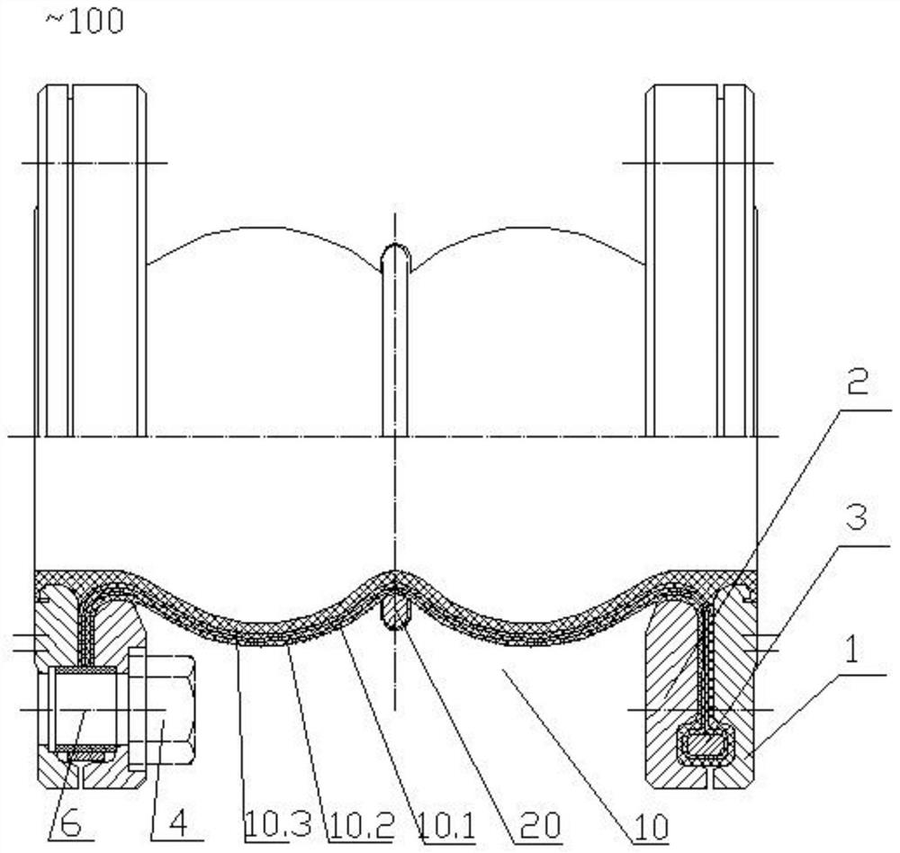
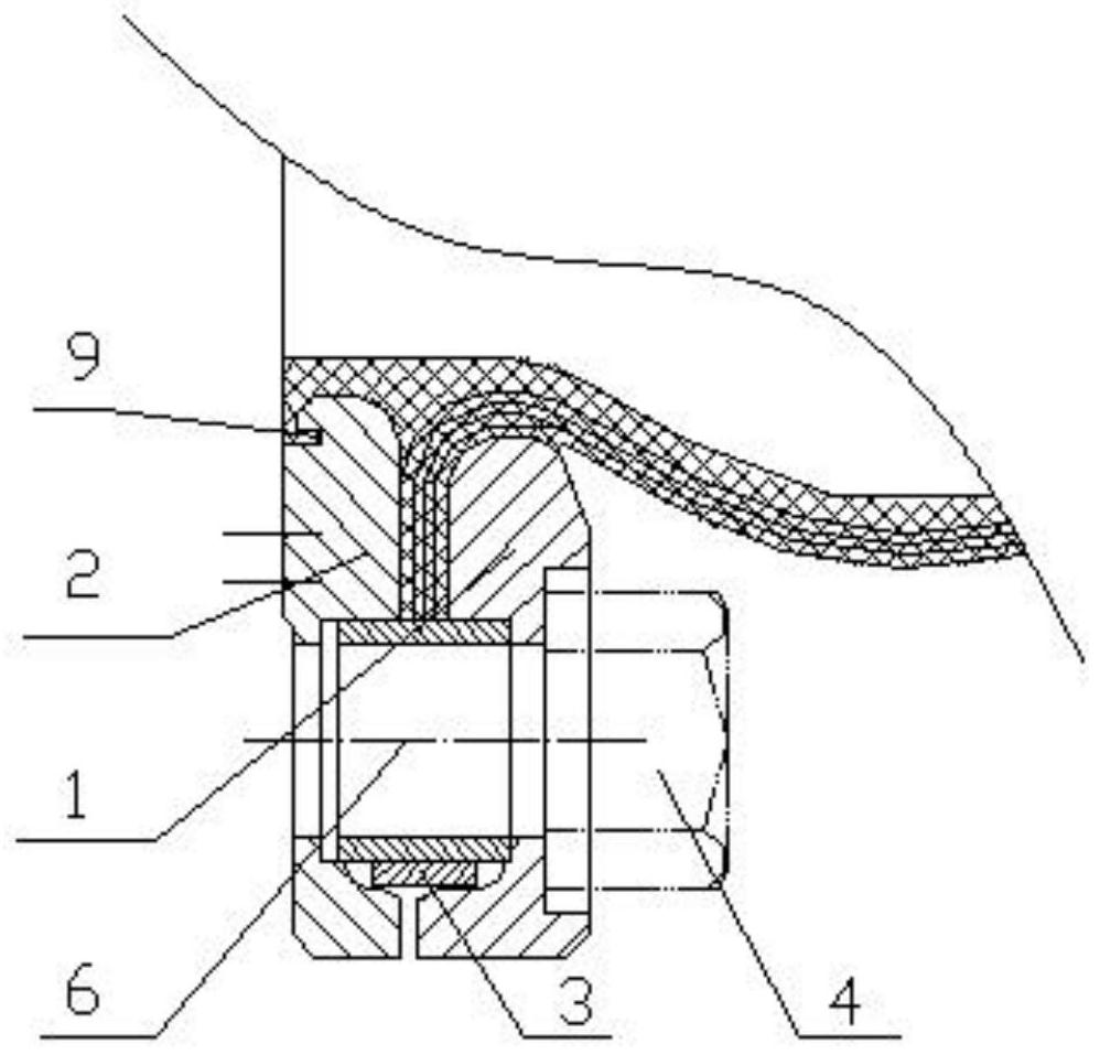
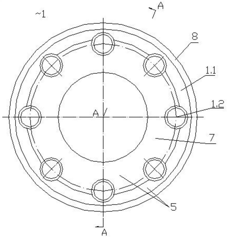
The invention discloses a self-locking type flange pair and a flexible connecting pipe. The self-locking type flange pair comprises a locking flange, a sealing flange and a fastening ring, wherein thelocking flange and the sealing flange are connected through a bolt, and a first annular groove formed in the outer side of the top surface of the locking flange is matched with a second annular groove formed in the outer side of the surface, close to the locking flange, of the sealing flange to form an annular cavity for containing the fastening ring; aramid fiber layers are arranged on the surfaces, close to each other, of the locking flange and the sealing flange respectively; and when the self-locking type flange pair is used for connecting the end of the flexible connecting pipe, the endof a framework layer of the flexible connecting pipe is turned outwards along the top surface of the locking flange and wound around the fastening ring by a circle, then the framework layer is lockedthrough the locking flange and the sealing flange corresponding to the framework layer, and the framework layer is pressed between the two aramid fiber layers. The self-locking type flange pair is simple in structure and small in size, the self-locking type flange pair is composed of the sealing flange, the fastening piece and the locking flange in a special combination mode, rigid sections can bereduced, the flexible length can be increased, and the self-locking type flange pair has excellent pull-out resistance and vibration reduction performance.

Description

technical field [0001] The invention relates to a flange joint structure, which belongs to the field of pipe joints in the shipbuilding industry, in particular to a self-locking flange pair and a flexible joint. Background technique [0002] At present, in the field of shipbuilding industry, in order to reduce or eliminate the vibration and noise generated by ships during transportation, products such as flexible joints and airbag vibration isolators are widely used. When designing and using these products, not only their load-bearing characteristics, dynamic characteristics, pressure resistance characteristics, etc., but also product specifications, weight, and joint reliability requirements should be considered. As a connecting part, the structure and performance of the flange directly affect the overall structure and performance of products such as flexible joints and airbag vibration isolators. [0003] The Naval Engineering University of the Chinese People's Liberation...

Claims


Application Information

Patent Timeline
Patent Type & Authority Applications(China)
IPC IPC(8): B29C70/34B29C70/54B29C35/02F16L11/112F16L27/10F16L27/111F16L33/28F16L55/02F16L57/02
CPCB29C70/342B29C70/54B29C35/02F16L27/1012F16L27/111F16L11/112F16L33/28F16L57/02F16L55/02
Inventor 程立全易岳辉杨鼎
Owner 湖北维普路船舶机电科技有限公司
Why Eureka
Eureka Blog
Learn More