High pressure sodium vapour lamp

A high-pressure sodium and steam technology, which is applied in the direction of discharge lamps, gas discharge lamps, parts of gas discharge lamps, etc., can solve the problems of increased lamp voltage deviation and prolonged stabilization time, and achieve the effect of suppressing dispersion

Inactive Publication Date: 2003-09-24
PANASONIC CORP
View PDF1 Cites 0 Cited by
  • Summary
  • Abstract
  • Description
  • Claims
  • Application Information

AI Technical Summary

Problems solved by technology

[0008] The first problem is that since the electrodes shield the heat generated by the arc discharge between the electrodes that becomes the heat source during lighting, the sodium amalgam held in the conductive tube is less likely to be heated, so the time required from lighting to stable lighting is prolonged.
[0009] The second problem is that since the temperature of the coldest part changes when the position of the conductive tube deviates during plugging, compared with the structure in which the sodium amalgam is placed at the inner end of the power tube where the temperature change is small, as shown in Figure 3 , the lamp voltage deviation increases during production

Method used


Image

  • High pressure sodium vapour lamp
  • High pressure sodium vapour lamp
  • High pressure sodium vapour lamp

Examples


no. 1 example

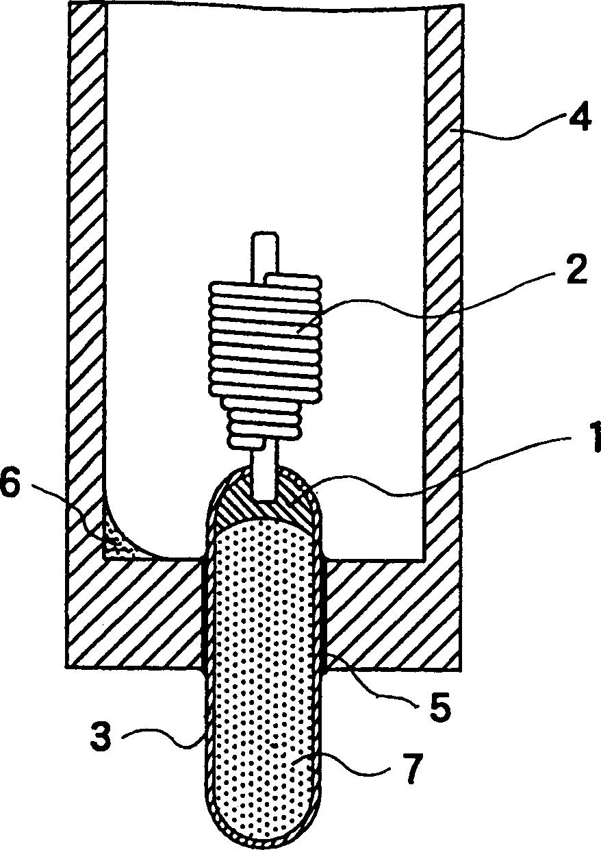
[0025] figure 1 It is a cross-sectional view showing the end structure of the light-emitting tube of a 150-watt high-pressure sodium vapor lamp with good lighting effect in an embodiment of the present invention. The structure of the luminous tube is that the conductive tube 3 supporting the electrode 2 is installed on both ends of the transparent alumina tube 4. in figure 1 In, only one end of the luminous tube is shown and the other end is omitted.

[0026] The electrode 2 with the electron radioactive material is fixed to one end of the conductive tube 3 in an airtight manner by the titanium brazing flux 1. The other end of the conductive tube 3 is closed, and the conductive tube 3 thus maintains an airtight structure. In the conductive tube 3, argon gas of 10 Torr at room temperature is enclosed as an inert gas. The conductive tube 3 is made of an alloy containing 99% niobium and 1% zirconium, and its outer diameter is 4 mm.

[0027] The installation part of the conductive ...

no. 2 example

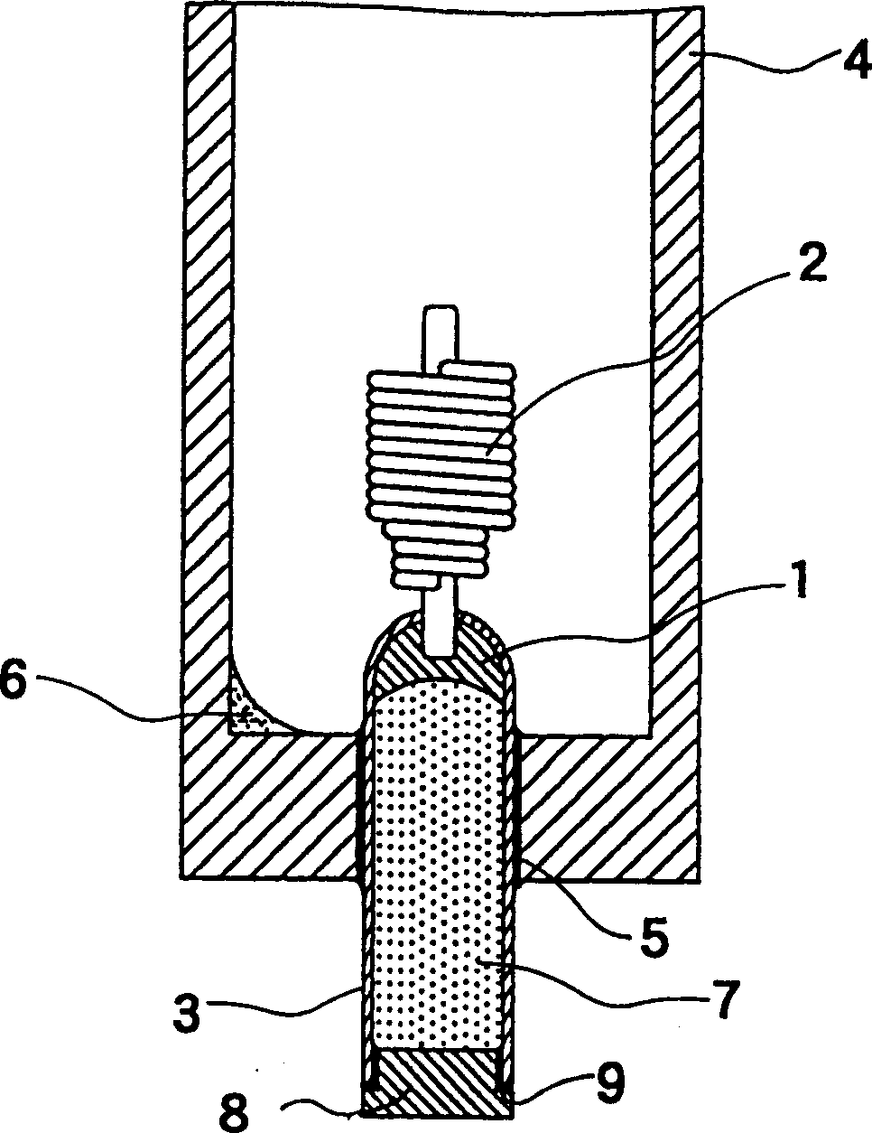
[0038] figure 2 It is a cross-sectional view showing the end structure of the light-emitting tube of a 150-watt high-pressure sodium vapor lamp with good lighting effect in another embodiment of the present invention. The luminous tube of the sodium vapor lamp of this embodiment is constructed in such a way that the opposite end of the electrode holding side of the conductive tube 3 is sealed with a ceramic cover 8 and a plugging agent 9 composed of ceramic glue, and an inert gas is sealed inside. The structure of the other parts is the same as the luminous tube of the sodium vapor lamp of the first embodiment.

[0039]In this way, an inert gas (argon) is enclosed at both ends of the conductive tube 3, and the conductive tube 3 is hermetically sealed in the light-transmitting alumina tube 4 with a plugging agent 5 to form a luminous tube. Prevents light color changes and lamp voltage changes in the course, shortens the time from lighting to lighting stabilization, and further sup...


PUM


Abstract

The electrode was airtightly fixed to one end of the conductive tube with titanium solder, and at the same time the other end of the conductive tube was closed, thereby forming the conductive tube airtightly, and argon gas was sealed inside. The conductive tube is hermetically sealed in a light-transmitting alumina tube with a sealing agent. Sodium amalgam is set in the light-transmitting alumina tube. The present invention can provide such a high-pressure sodium vapor lamp, that is, while preventing the deformation of the conductive tube, by arranging the luminescent substance sodium in the luminous tube, the light color change and the lamp voltage change during the journey can be prevented, and the time required from lighting to lighting stability can be shortened. time and suppress the dispersion of the lamp voltage.

Description

Technical field [0001] The invention relates to a high-pressure sodium vapor lamp, in particular to a luminous tube structure of a high-pressure sodium vapor lamp with good lighting effect. Background technique [0002] An example of the luminous tube structure of a conventional high-pressure sodium vapor lamp is shown in FIG. 3. The conventional high-pressure sodium vapor lamp has a conductive tube 33 and an electrode 32 fixed to one end of the conductive tube 33 by using a titanium solder 31. In addition, the other end of the conductive tube 33 serves as an open end. [0003] The conductive tube 33 is installed on one end of the light-transmitting alumina tube 34, and the mounting part of the conductive tube 33 in the light-transmitting alumina tube 34 is hermetically sealed by a plugging agent 35 made of ceramic glue. The sodium amalgam 36 is enclosed in the inner end of the light-transmitting alumina tube 34. [0004] In the above-mentioned traditional luminous tube structure...

Claims


Application Information

Patent Timeline
Patent Type & Authority Patents(China)
IPC IPC(8): H01J61/073H01J61/36H01J61/82
CPCH01J61/0732H01J61/36H01J61/825
Inventor 和田雅人田久保章夫
Owner PANASONIC CORP
Why Eureka
Try Eureka