Capacitor microphone assembly

A technology of condenser microphone and electro-acoustic transducer, applied in electrostatic transducer microphone, electret electrostatic transducer and other directions, can solve problems such as poor performance

Inactive Publication Date: 2007-06-06
AUDIO-TECHNICA
View PDF1 Cites 0 Cited by
  • Summary
  • Abstract
  • Description
  • Claims
  • Application Information

AI Technical Summary

Problems solved by technology

In extreme cases, gaps are sometimes formed between the electret plate 21a and the gasket 30, and between the diaphragm 11 and the gasket 30, resulting in poor performance.

Method used


Image

  • Capacitor microphone assembly
  • Capacitor microphone assembly
  • Capacitor microphone assembly

Examples


Embodiment Construction

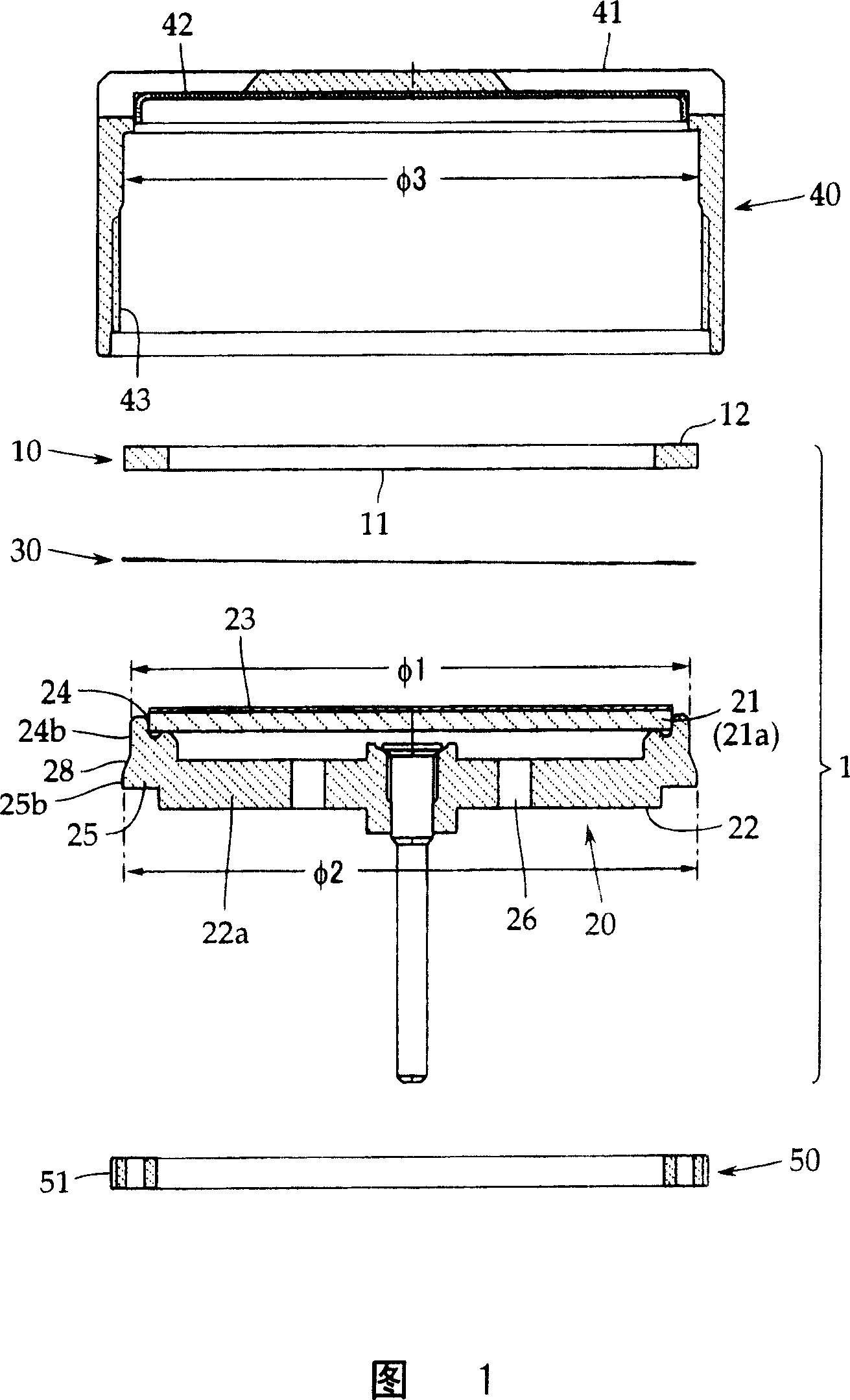
[0026] Hereinafter, an embodiment of the present invention will be described using FIG. 1 , but the present invention is not limited thereto. Fig. 1 is an exploded sectional view showing an embodiment of a condenser microphone unit of the present invention. In addition, the same reference numerals are used for components that do not need to be changed from the conventional example described above in FIG. 2 .

[0027] As shown in FIG. 1 , this condenser microphone unit includes, as a basic configuration, an electroacoustic transducer 1 including a diaphragm assembly 10, a fixed pole assembly 20, and an electrically insulating spacer 30 disposed therebetween. ; the assembly case 40 for the electroacoustic transducer 1 ; the locking ring 50 as a fastening and fixing mechanism for fastening and fixing the electroacoustic transducer 1 in the assembly case 40 . In addition, the condenser microphone unit in this example is a back-electret type in which the fixed pole is formed of an...


PUM


Abstract

When the electroacoustic converter which is formed by contraposition through a gasket of a diaphragm assembling body and a fixing pole assembling body, is fixed in assembly case, the inner stess will not bring dispersion while fixed. A capacitor microphone assembly, is produced by hard fixing the electroacoustic converter by a locked-in loop in the assembly case. The said electroacoustic converter is formed by contraposition through a gasket of a diaphragm assembling body provided with a diaphragm on the supporting ring, and a fixing pole assembling body provided with a fixing pole on the insulated seat, wherein, A smaller external diameter of the cylinder porition is formed in advance, in order to not expand the periphery surface of the cylinder porition larger than inner diameter of the assembly case, when the fixing pole is pressed into the cylinder porition provided in the insulated seat.

Description

technical field [0001] The present invention relates to a condenser microphone assembly. When fastening and fixing an electroacoustic transducer formed by disposing a vibrating membrane assembly and a fixed pole assembly opposite to each other through a liner in the assembly box, the internal stress will not be discrete during fastening. . Background technique [0002] As shown in FIG. 2 , the condenser microphone assembly includes an electroacoustic transducer 1, and the electroacoustic transducer 1 is arranged opposite to a diaphragm assembly 10 in which a diaphragm 11 is stretched on a support ring 12 with a predetermined tension and fixed The pole 21 is supported by the fixed pole assembly 20 on the insulating seat 22 made of synthetic resin, and an electrically insulating spacer 30 is interposed between the diaphragm assembly 10 and the fixed pole assembly 20 . [0003] The actual assembly is carried out in such a manner that after the diaphragm assembly 10, the spacer...

Claims


Application Information

Patent Timeline
IPC IPC(8): H04R19/01H04R19/04
Inventor 秋野裕
Owner AUDIO-TECHNICA
Why Eureka
Try Eureka