
A positioning platform for ultra-precise fast machining with large load

A positioning table, ultra-precision technology, applied in metal processing equipment, tool holders, manufacturing tools, etc., can solve problems such as difficulty in achieving high precision and micron-level dimensional processing, inability to achieve large load and rapid processing, and low stiffness in the direction of movement. , to achieve the effect of avoiding errors, convenient replacement and good stability

Active Publication Date: 2022-02-11
HARBIN CORE TOMORROW SCI & TECH
View PDF15 Cites 0 Cited by
  • Summary
  • Abstract
  • Description
  • Claims
  • Application Information

AI Technical Summary

Problems solved by technology

[0003] At present, in the industry, the use of complex curved surface parts is becoming more and more frequent. Conventional machine tool processing is difficult to achieve high precision and micron-level size processing, and traditional cutting tools are fed in a large range, with low precision and slow feeding speed. The piezo-ceramic-driven fast knife is directly driven by the piezoelectric ceramic to the flexible hinge, the hinge is easily damaged, and the stiffness in the direction of motion is low, and the anti-interference ability is weak, which will increase the feed error of the fast knife
For example, the existing fast-knife servos and fast-knife servos with adjustable stiffness are ceramic direct drive hinges, the hinges are easily damaged, the anti-interference ability is weak, and the weight of the tools that can be carried is limited, and it is impossible to achieve large-load rapid processing

Method used


Image

  • A positioning platform for ultra-precise fast machining with large load
  • A positioning platform for ultra-precise fast machining with large load
  • A positioning platform for ultra-precise fast machining with large load

Examples


Embodiment Construction

[0033] It should be noted that, in the case of no conflict, the embodiments of the present invention and the features in the embodiments can be combined with each other.

[0034] The present invention will be described in detail below with reference to the accompanying drawings and examples.

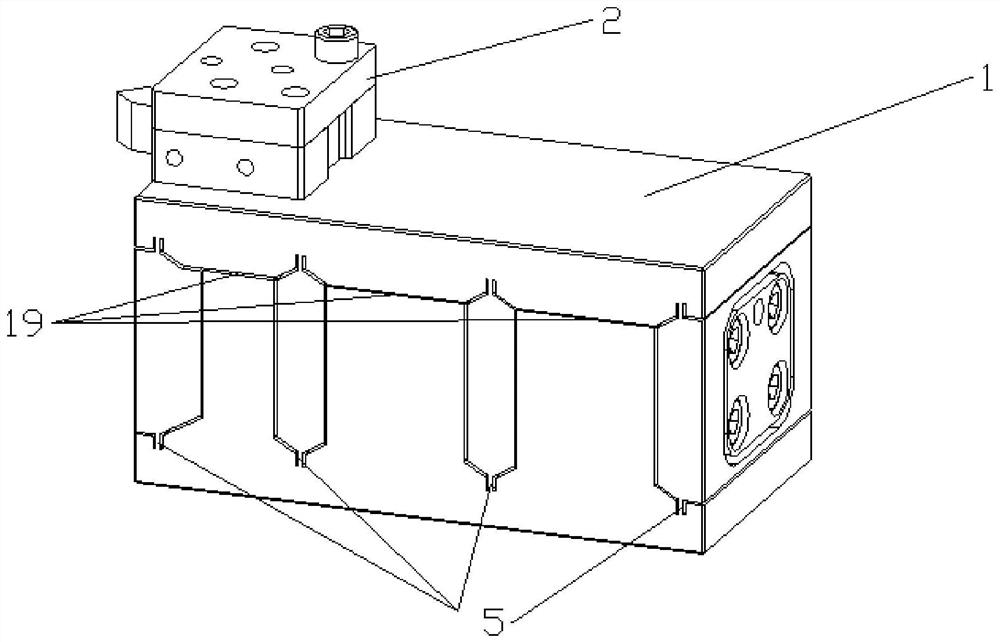
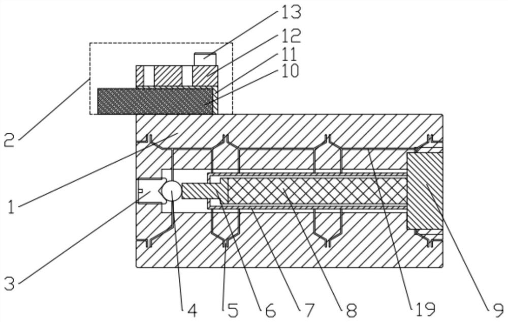
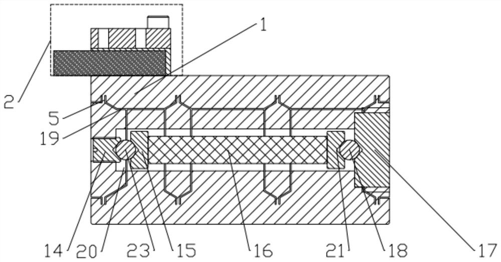
[0035] Such as Figure 1-Figure 5 As shown, a large-load ultra-precision rapid machining positioning table includes a fast-knife main table body 1 and a tool assembly 2, and the knife assembly 2 is installed on the upper left side of the fast-knife main table body 1. 1 is a cuboid structure, in the center of the main table body 1 of the fast knife, a stepped hole 20 in the middle of the table body is opened through the left and right end faces, and several flexible hinges 5 are formed by cutting the main table body 1 of the fast knife from the front end surface of the main table body 1 of the fast knife to the rear end surface. , cutting the flexible hinge 5 to form several cutting seam...


PUM


Abstract

The invention provides a positioning table for large-load ultra-precision rapid processing, which includes a main table body of a fast knife and a tool assembly. The tool assembly is installed above the left side of the main table body of a fast knife. The center of the main table body is provided with a stepped hole in the middle of the table body that runs through the left and right end faces, and cuts the main table body of the fast knife from the front face of the main table body of the sharp knife to the rear end face to form a number of flexible hinges, and cuts the flexible hinges to form a number of cutting seams; each flexible hinge Arranged from the upper part to the lower part of the main table body of the fast knife; on the front and rear end faces of the main table body of the fast knife between two adjacent flexible hinges, there are elongated cutting holes, and each elongated cutting hole communicates with the adjacent cutting The cutting seam formed by the flexible hinge; the driving element is installed in the stepped hole in the middle of the table body, and the driving element drives the upper part of the main table body of the fast knife to produce a slight displacement, and drives the movement of the knife assembly. The invention has the characteristics of ultra-high precision, large stroke, high rigidity and fast response speed.

Description

technical field [0001] The invention belongs to the technical field of precision machining, and in particular relates to a large-load ultra-precision fast machining positioning table. Background technique [0002] Microstructured surface optical components are widely used in military, aerospace, energy and other fields, and are the core components of optoelectronic systems. Traditional multi-axis milling is difficult to meet the processing accuracy and low efficiency, and other new processing methods also have various deficiencies, and the use of ultra-precision turning technology can directly turn and process the microstructure surface with nanometer precision. The fast tool servo tool holder is the key to machining the microstructure surface. It determines the complexity of the microstructure surface that the system can process and the surface accuracy after machining. Therefore, the fast tool positioning system must be able to achieve high-speed and high-precision feeding...

Claims


Application Information

Patent Timeline
Patent Type & Authority Patents(China)
IPC IPC(8): B23B27/00B23B29/04
CPCB23B29/04B23B27/00
Inventor 陈峰闫巍徐国飞杨明远
Owner HARBIN CORE TOMORROW SCI & TECH
Learn More