Eureka AIR delivers breakthrough ideas for toughest innovation challenges, trusted by R&D personnel around the world.

Liquid food feeding device

A food and liquid technology, applied in the direction of therapeutic feeding tubes, etc., can solve the problems of poor use effect, single function, inconvenient direction fine-tuning, etc., to achieve the effect of improving practical performance, uniform liquid food material, and improving intelligence

Pending Publication Date: 2021-01-15
JIANGSU CANCER HOSPITAL
View PDF8 Cites 3 Cited by
  • Summary
  • Abstract
  • Description
  • Claims
  • Application Information

AI Technical Summary

Problems solved by technology

[0002] After gastric surgery, esophagus surgery, throat surgery and other operations, patients can only eat a small amount of liquid food when they need to eat. At present, most of the liquid food eating methods are through test tube feeding, which requires medical staff to control the speed and speed of eating according to the patient's condition. Some inexperienced medical personnel or family members cannot complete it, and may even cause secondary harm to patients
[0003] However, the existing liquid food feeding device has a single function, which cannot be completed by medical personnel or family members with little experience, and may even cause secondary injury to the patient. It becomes cold, affects eating, and cannot meet people's needs, etc.
[0004] At the same time, the nasogastric tube used has a simple tubular structure. When inserted into the patient's stomach through the nasal cavity, the front end of the tube is likely to cause discomfort, and the front end of the ordinary nasogastric tube is inconvenient to fine-tune the direction. Psychological fear, the use effect is poor

Method used


Image

  • Liquid food feeding device
  • Liquid food feeding device
  • Liquid food feeding device

Examples


Embodiment Construction

[0040] The present invention will be further described below in conjunction with accompanying drawing.

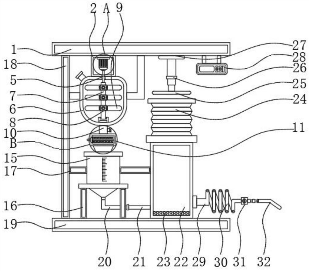
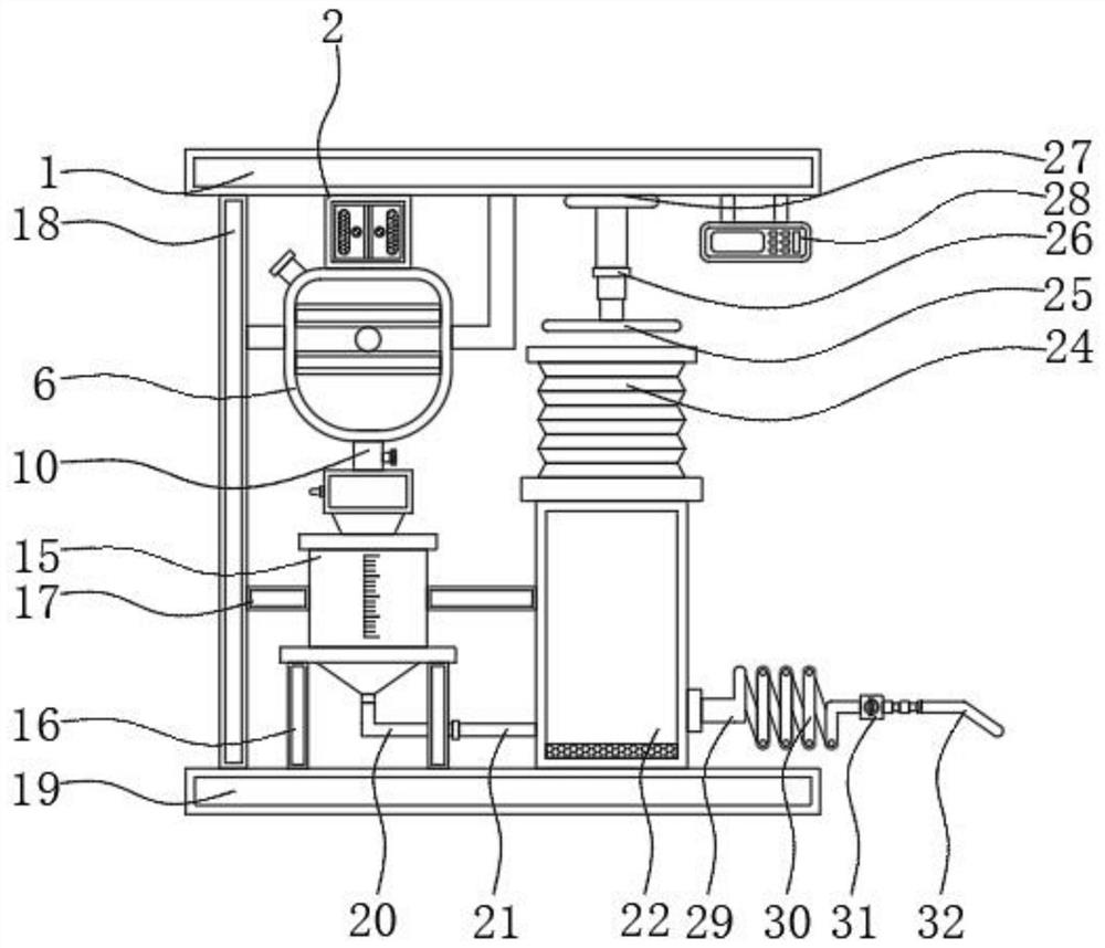
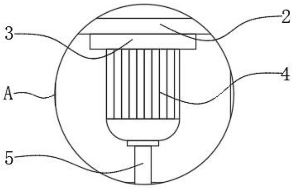
[0041] see Figure 1 to Figure 14 , the present invention provides a technical solution: a liquid food feeding device, including a top plate 1 and a mixing bucket 6, a protective cover 2 is fixedly connected to the bottom of the top plate 1, and a mounting seat 3 is fixedly connected to the inside of the protective cover 2, and the top plate 1 The lower surface of the protective cover 2 is closely attached to the upper surface of the protective cover 2, and the central axis of the protective cover 2 coincides with the central axis of the motor 4. The motor 4 is fixedly connected to the bottom of the mounting base 3, and the motor 4 is fixedly connected to the bottom of the motor 4. There is a stirring shaft 5, and the motor 4 forms a rotating structure through the stirring shaft 5 and the connecting rod 7, and the connecting rod 7 is vertically placed on the lower surface o...


PUM


Abstract

The invention discloses a liquid food feeding device which comprises a top plate, a stirring barrel and a nasogastric tube, a protective cover is fixedly connected to the lower portion of the top plate, a mounting base is fixedly connected to the interior of the protective cover, a motor is fixedly connected to the lower portion of the mounting base, a stirring shaft is fixedly connected to the lower portion of the motor, the stirring barrel is located under the protective cover, a connecting rod is movably connected to the interior of the stirring barrel, a stirring base is movably connectedto the outer wall of the connecting rod, stirring blades are fixedly connected to the left side and the right side of the stirring base, a discharging hopper is fixedly connected to the lower portionof the stirring barrel, and a filtering cabin is fixedly connected to the lower portion of the discharging hopper. According to the invention, the device effectively realizes the liquid food feeding,and can be conveniently inserted into the stomach of patient at the same time, the discomfort degree in the intubation process is small, and the application effect is good.

Description

technical field [0001] The present invention relates to a liquid food feeding device. Background technique [0002] After gastric surgery, esophagus surgery, throat surgery and other operations, patients can only eat a small amount of liquid food when they need to eat. At present, most of the liquid food eating methods are through test tube feeding, which requires medical staff to control the speed and speed of eating according to the patient's condition. Some inexperienced medical personnel or family members cannot complete it, and may even cause secondary harm to patients. [0003] However, the existing liquid food feeding device has a single function, which cannot be completed by medical personnel or family members with little experience, and may even cause secondary injury to the patient. It becomes cold, affects eating, and can not meet people's needs for use. [0004] At the same time, the nasogastric tube used has a simple tubular structure. When inserted into the p...

Claims


Application Information

Patent Timeline
IPC IPC(8): A61J15/00
CPCA61J15/0003A61J15/0026A61J15/0061A61J15/0092
Inventor 蔡宏宙胡云徐维章
Owner JIANGSU CANCER HOSPITAL
Why Eureka
Eureka Blog
Learn More