
Series alternate residual oil hydrotreatment-catalytic cracking combined process method and system

A catalytic cracking and hydrotreating technology, which is applied in hydrotreating process, hydrocarbon oil treatment products, petroleum industry, etc. It can solve the problems of increasing the load of heating furnace, insufficient capacity of dirt and impurities, and affecting the catalytic activity of the main catalyst.

Active Publication Date: 2021-01-12
CHINA PETROLEUM & CHEM CORP +1
View PDF6 Cites 0 Cited by
  • Summary
  • Abstract
  • Description
  • Claims
  • Application Information

AI Technical Summary

Problems solved by technology

However, after parallel and series operation, the method needs to stop and replace the catalysts of each hydrogenation pretreatment reactor, and requires a long shutdown time, and cannot continue hydrogenation of residual oil for a long time, thereby affecting the economic efficiency of the refinery; , the pressure drop of each hydrogenation pretreatment reactor is at the highest level in the late stage of operation, and it is also operated in series, which makes the total pressure drop of hydrogenation pretreatment very high. If the original operating conditions are maintained, it will affect the main The catalytic activity of the catalyst, this loss of catalytic activity is irreversible
In order to ensure the catalytic activity of the main catalyst, it is necessary to further increase the reaction severity of the front hydrogenation pretreatment and increase the reaction temperature to a greater extent, which will increase the load on the heating furnace. Sometimes the original design load may be too small to meet heating requirements
[0007] In the above residual oil hydrogenation process, when the fixed bed is filled with hydrogenation protecting agent and hydrodemetallization catalyst at the same time, if a lower proportion of hydrodemetallation agent is used, the hydrodemetallization performance of the entire catalyst system is insufficient, especially At the end of the operation, the metal-accommodating capacity is low, which leads to the rapid deactivation of the catalyst in the main reaction zone, which is not conducive to the long-term operation of the device; Insufficient scale and impurity capacity of the hydrogenation pretreatment reactor leads to a rapid rise in the pressure drop of the hydrogenation pretreatment reactor, shortens the normal operation time, and soon enters the end of operation, resulting in shutdown, which is also not conducive to the long-term operation of the device

Method used


Image

  • Series alternate residual oil hydrotreatment-catalytic cracking combined process method and system
  • Series alternate residual oil hydrotreatment-catalytic cracking combined process method and system
  • Series alternate residual oil hydrotreatment-catalytic cracking combined process method and system

Examples


Embodiment 1

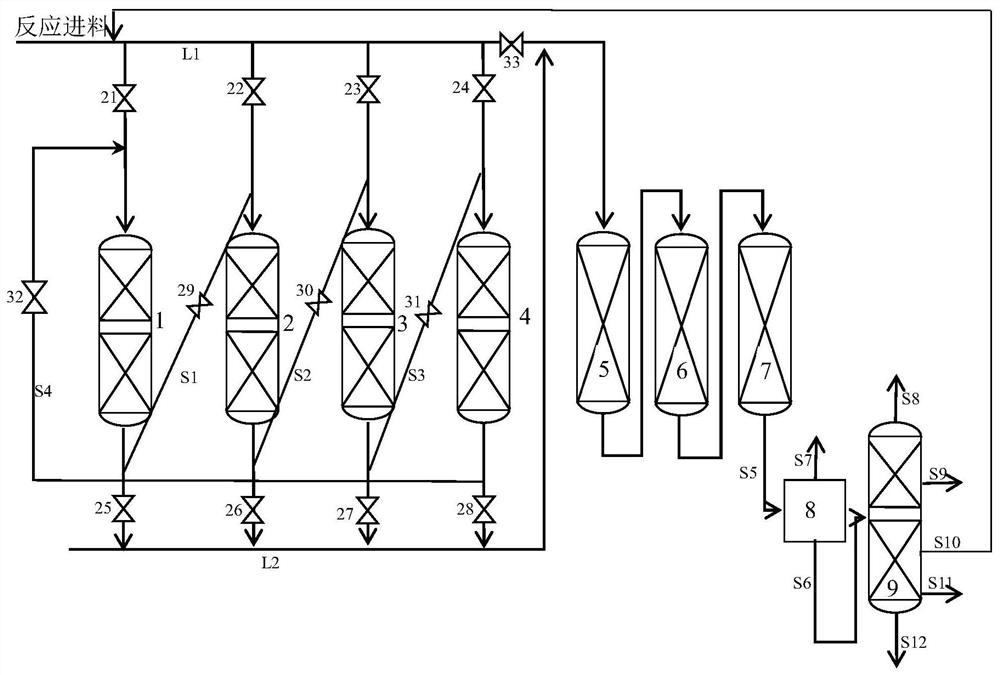
[0066] This embodiment adopts as figure 1 Shown reaction system, concrete reactor and connection relation are as follows:

[0067] The reaction system includes a first hydrotreating reactor 1, a second hydrotreating reactor 2, a third hydrotreating reactor 3, a hydrotreating reactor 5, a hydrotreating reactor 6, a hydrotreating Reactor 7. The main reaction feed pipeline L1 is connected with the first hydrogenation pretreatment reactor 1, the second hydrogenation pretreatment reactor 2, and the third hydrogenation pretreatment reactor 3 through the valve body 21, the valve body 22, and the valve body 23 respectively. The inlets are connected, and the outlets of the first hydrogenation pretreatment reactor 1, the second hydrogenation pretreatment reactor 2, and the third hydrogenation pretreatment reactor 3 are respectively connected with the reaction outlet through the valve body 24, the valve body 25, and the valve body 26. The main feed pipeline L2 is connected, and the fir...

Embodiment 2

[0094] This embodiment adopts as figure 2 Shown reaction system, concrete reactor and connection relation are as follows:

[0095] The reaction system comprises a first hydroprocessing reactor 1, a second hydroprocessing reactor 2, a third hydroprocessing reactor 3, a fourth hydroprocessing reactor 4, a hydroprocessing reactor 5, Hydrotreating reactor 6, Hydrotreating reactor 7. The main reaction feed pipeline L1 is connected with the first hydrogenation pretreatment reactor 1, the second hydrogenation pretreatment reactor 2, and the third hydrogenation pretreatment reactor through valve body 21, valve body 22, valve body 23, and valve body 24, respectively. Reactor 3, the inlet of the fourth hydrogenation pretreatment reactor 4 are connected, the first hydrogenation pretreatment reactor 1, the second hydrogenation pretreatment reactor 2, the third hydrogenation pretreatment reactor 3, the fourth hydrogenation pretreatment reactor The outlet of the hydrogen pretreatment rea...

Embodiment 3

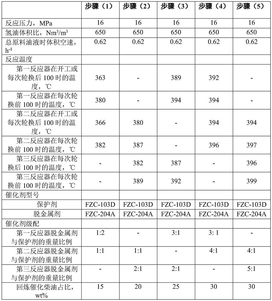
[0120] This example adopts the reaction system, reaction raw materials and reactor rotation method of Example 1, the difference is: the first hydrogenation pretreatment reactor 1, the second hydrogenation pretreatment reactor 2, the third hydrogenation pretreatment The ratio of demetallization agent to protective agent in reactor 3 is 1:1, and remains unchanged for each rotation. The switching time of the hydrogenation pretreatment reactor is shown in Table 6. All catalytic cracking diesel fractions obtained after the catalytic cracking reaction are mixed with residual oil raw materials and enter the hydrogenation pretreatment reaction zone for reaction. Among them, based on the total weight of residual oil feedstock and catalytic cracking diesel oil fraction entering the hydrogenation pretreatment reaction area, the catalytic cracking diesel oil fraction returned to the hydrogenation pretreatment reaction area accounts for 30wt%.

[0121] Among them, the properties of the cat...


PUM


Abstract

The invention discloses a series alternate residual oil hydrotreatment-catalytic cracking combined process method and system. The method comprises the following steps: mixing a residual oil raw material and at least part of a catalytically cracked diesel fraction with hydrogen, allowing the obtained mixture to sequentially pass through a hydrogenation pretreatment zone and a hydrotreating reactionzone which are connected in series, carrying out gas-liquid separation on the reaction effluent of the hydrotreating reaction zone, and allowing the separated liquid phase to directly enter a catalytically cracked reaction zone to carry out a catalytic cracking reaction. The hydrogenation pretreatment reaction zone comprises N hydrogenation pretreatment reactors, the first hydrogenation pretreatment reactor to the N-1th hydrogenation pretreatment reactor are sequentially connected in series and are used as N1-stage online hydrogenation pretreatment reactors, and the Nth hydrogenation pretreatment reactor is used as an offline hydrogenation pretreatment reactor. According to the method and the system, the operation time of the hydrotreating pretreatment process is long without shutdown, the stable exertion of the overall catalytic activity of the hydrotreating main catalyst is facilitated, reasonable and limited alternating times are ensured, and the operation time and the working efficiency of the hydrotreating reactor are prolonged.

Description

technical field [0001] The invention relates to a residual oil hydrotreating-catalytic cracking combined process method and system, in particular to a residue oil hydrotreating-catalytic cracking combined process method and system which can be rotated in series. Background technique [0002] As crude oil becomes heavier and worse, more and more heavy oil and residual oil need to be processed. The main purpose of the residue oil hydrotreating process is to greatly reduce the content of impurities such as sulfur, nitrogen, and metals in the residue oil raw material through hydrogenation treatment, and to convert non-ideal components such as polycyclic aromatics, colloids, and asphaltenes through hydrogenation. Increase the hydrogen-to-carbon ratio, reduce the residual carbon content, and significantly improve the cracking performance. [0003] Fixed bed residual oil hydrogenation technology is a deep processing technology for heavy oil. Under the condition of high temperature...

Claims


Application Information

Patent Timeline
Patent Type & Authority Applications(China)
IPC IPC(8): C10G69/04
CPCC10G69/04C10G2300/1037C10G2300/1048C10G2300/1055C10G2300/1059C10G2300/107C10G2300/1077C10G2400/02C10G2400/04
Inventor 翁延博耿新国刘铁斌李洪广金建辉韩坤鹏
Owner CHINA PETROLEUM & CHEM CORP
Learn More