
Metal pipe section deburring device for electromechanical machining

A metal pipe, electromechanical technology, applied in the field of metal pipe deburring devices for electromechanical processing, can solve the problems of wasting time, health effects of workers, etc., and achieve the effect of improving efficiency

Inactive Publication Date: 2021-01-12
SUZHOU WABOTE INTELLIGENT TECH CO LTD
View PDF0 Cites 5 Cited by
  • Summary
  • Abstract
  • Description
  • Claims
  • Application Information

AI Technical Summary

Problems solved by technology

[0005] The object of the present invention is to provide a metal pipe section deburring device for electromechanical processing that can automatically deburr metal pipes and has a fast deburring speed, so as to solve the problem that the existing deburring methods require manual deburring, which is a waste of time , and the dust generated during deburring is likely to affect the health of the staff

Method used


Image

  • Metal pipe section deburring device for electromechanical machining
  • Metal pipe section deburring device for electromechanical machining
  • Metal pipe section deburring device for electromechanical machining

Examples


Embodiment 1

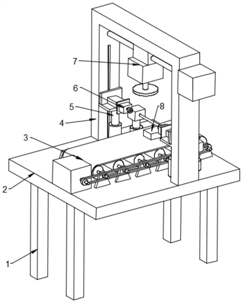
[0025] Such as figure 1 As shown, in one embodiment of the present invention, a metal pipe segment deburring device for electromechanical processing includes a support frame 1, a workbench 2 is arranged on the support frame 1, and a conveying device is arranged on the workbench 2 3. The workbench 2 is provided with a grinding frame 4 on both sides of the conveying device 3, the upper part of the grinding frame 4 is provided with a grinding device 7, and the lower part of the grinding frame 4 is provided with two lifting devices 5 distributed in mirror images. A clamping and rotating device 6 is provided on the lifting device 5 , and a blocking device 8 is provided on the upper side of the conveying device 3 .

[0026] In one embodiment of the present invention, when in use, the metal pipe can be directly placed on the conveying device 3, and the metal pipe is driven by the conveying device 3 to move, and when it reaches the position of the blocking device 8, it is blocked, and...

Embodiment 2

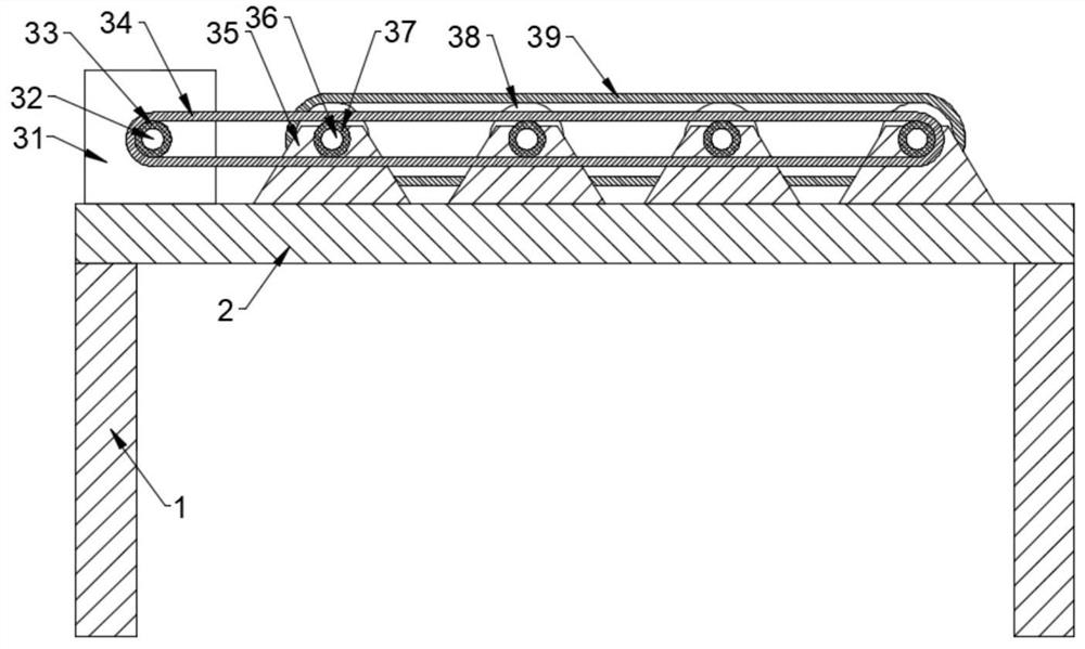
[0028] Such as figure 1 and 2 As shown, in another embodiment of the present invention, the conveying device 3 includes a first driving device 31, the first driving device 31 is arranged on the worktable 2, and the first driving device 31 passes through the driving shaft 32 Connected with a driving wheel 33, the driving wheel 33 cooperates with a plurality of groups of driven wheels 37 through a belt 34, and the inside of the driven wheel 37 is provided with a driven shaft 36, and the driven shaft 36 is rotatably connected to the support seat 35, so The bottom of the support seat 35 is fixed on the workbench 2, the driven shaft 36 is provided with a transmission roller 38, and the transmission roller 38 is equipped with a crawler belt 39; when the transmission device 3 is working, the first driving device 31 passes through the driving shaft 32 drives the driving wheel 33 to rotate, and the driving wheel 33 drives the driven wheel 37 to rotate through the belt 34, and the driv...

Embodiment 3

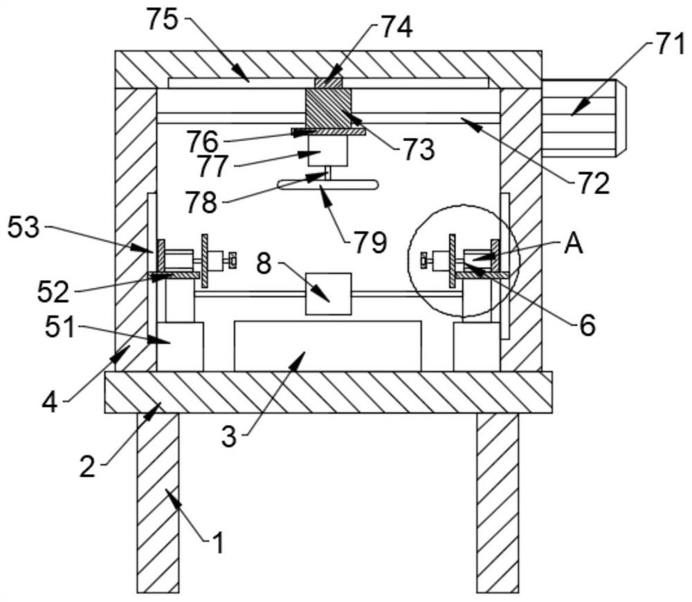
[0030] Such as image 3 and 4 As shown, in another embodiment of the present invention, the lifting device 5 includes a first telescopic rod 51, the bottom of the first telescopic rod 51 is fixed on the workbench 2, and the top of the first telescopic rod 51 is provided with Support plate 52, one end of the support plate 52 is slidingly fitted in the lifting groove 53, the lifting groove 53 is arranged on the side of the grinding frame 4, and the clamping and rotating device 6 is arranged on the supporting plate 52; 6 Clamp the metal pipe, and then the first telescopic rod 51 rises or falls to drive the support plate 52 to rise or fall along the interior of the lifting groove 53, thereby adjusting the height of the metal pipe. Since the support plate 52 is provided with a clamping device, the support plate 52 is used to 52 cooperates with the structure of the lifting groove 53 to ensure more stable clamping and more stable lifting.

[0031] In one embodiment of the present i...


PUM


Abstract

The invention relates to the technical field of electromechanical machining, in particular to a metal pipe section deburring device for electromechanical machining. The metal pipe section deburring device comprises a workbench, a conveying device is arranged on the workbench, grinding frames are arranged at the positions, located on the two sides of the conveying device, of the workbench, grindingdevices are arranged on the upper portions of the grinding frames, two lifting devices which are distributed in a mirror image mode are arranged below the grinding frames, clamping rotating devices are arranged on the lifting devices, and a blocking device is further arranged on the upper side of the conveying device. The metal pipe section deburring device has the advantages that a metal pipe isdriven by the conveying device to move and is blocked by the blocking device, then the clamping rotating devices clamp the metal pipe, the lifting devices drive the metal pipe to ascend, the clampingrotating devices drive the metal pipe to rotate, and meanwhile, the grinding devices at the top carry out comprehensive grinding on the metal pipe, after grinding, the lifting devices drive the metalpipe to descend, and meanwhile, the blocking device ascends, the ground metal pipe is released, the deburring operation can be carried out on the metal pipe very quickly, and the deburring efficiencyis improved.

Description

technical field [0001] The invention relates to the technical field of electromechanical processing, in particular to a deburring device for metal pipe segments used in electromechanical processing. Background technique [0002] Some of the burrs on mechanical parts are caused by plastic deformation in the cutting process; In the field of processing, especially in the fields of aviation, aerospace, and instrumentation, with the improvement of the manufacturing precision of mechanical parts and the miniaturization of mechanism design, the harmfulness of burrs is particularly obvious. and removal methods. [0003] However, the existing deburring methods all need to be manually removed, which is a waste of time, and the dust generated during deburring is likely to have an impact on the health of the staff. [0004] Therefore we need a kind of metal pipe segment deburring device for electromechanical processing that can automatically deburr the metal pipe and has a fast deburr...

Claims


Application Information

Patent Timeline
Patent Type & Authority Applications(China)
IPC IPC(8): B24B27/00B24B27/02B24B41/00B24B9/04B24B55/06B24B41/02B24B41/06B24B5/36B24B5/35
CPCB24B27/0046B24B27/02B24B41/005B24B9/04B24B55/06B24B41/02B24B41/067B24B5/363B24B5/355B24B9/007
Inventor 徐政
Owner SUZHOU WABOTE INTELLIGENT TECH CO LTD
Learn More