Heat treatment process oil gas recovery device and method

A technology of heat treatment process and recovery device, which is applied in the field of metal processing, can solve problems such as large power consumption, heat loss, air pollution, etc., and achieve the effects of reducing oil and gas emissions, slowing down high-temperature oxidation, and realizing recycling

Active Publication Date: 2020-12-29
南京五域化工科技有限公司
View PDF9 Cites 1 Cited by
  • Summary
  • Abstract
  • Description
  • Claims
  • Application Information

AI Technical Summary

Problems solved by technology

According to the type and size of the aluminum foil, the heat treatment process of the aluminum foil usually takes 1-15 days, and precise heating and heat preservation in the furnace is required, generally at 200-230°C. Blowing in air and discharging high-temperature oil and gas will inevitably cause heat loss in the furnace, which requires a lot of power consumption to control the temperature
Therefore, in the current heat treatment process of aluminum foil processing, based on an average of 1-5kg of rolling oil per ton of aluminum foil, 10-50 tons of VOC will be produced for every 10,000 tons of aluminum foil produced. These rolling oils contain aromatics and sulfur. It will cause serious pollution to the atmosphere; in addition, the continuous use of normal temperature air to replace the high temperature oil and gas in the furnace will cause a lot of waste of electricity

Method used


Image

  • Heat treatment process oil gas recovery device and method
  • Heat treatment process oil gas recovery device and method
  • Heat treatment process oil gas recovery device and method

Examples


Embodiment 1

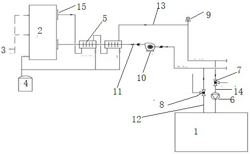
[0030] Such as figure 2 As shown, in a heat treatment furnace 1, put 25 tons of aluminum foil at a time, but connect the exhaust pipe and intake pipe of the heat treatment furnace to the system described in the manual, and open the valve at the inert gas inlet 3, so that the deep The cooler is filled with inert gas, the second fan 10 is turned on, the second three-way valve 8 is opened, the exhaust pipe 12 is communicated with the atmosphere, the first fan 6 is turned on, the inert gas enters the heat treatment furnace 1, and the air is discharged from the second After the second three-way valve 8 is extruded, the second three-way valve 8 is adjusted to be connected to the exhaust pipe 12, and the gas enters the heat exchanger group, so that the inert gas continues to circulate with the operation of the fan, and the inert gas inlet 3 is closed. The valve at the cryocooler 2 sprays liquid inert gas, heat treatment, heating and heat preservation according to the process establi...

Embodiment 2

[0034] Such as image 3 As shown, the exhaust pipes and intake pipes of the two heat treatment furnaces are connected to the system of the present invention. The two heat treatment furnaces can produce synchronously or in staggered steps, and can be adjusted by valves without interfering with each other.

[0035] The working process of the two heat treatment furnaces opens the valve at the inert gas inlet 3, makes the cryocooler 2 full of gas carbon dioxide, turns on the second fan 10, turns on the second fan 10, opens the second three-way valve 8, and makes the exhaust The trachea 12 communicates with the atmosphere, and the first blower 6 is turned on so that the carbon dioxide enters the heat treatment furnace 1 and the air is extruded from the second three-way valve 8, and the second adjusted gas is connected to the sub-exhaust pipeline 12, and after the general exhaust The gas pipe 11 enters the heat exchanger group, so that the carbon dioxide gas is continuously circulat...

Embodiment 3

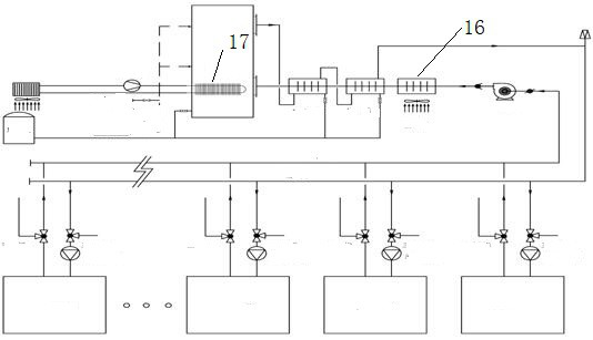
[0039] Such as figure 1 As shown, the exhaust pipes and intake pipes of n heat treatment furnaces (n≥3) are connected to the system of the present invention, and the n heat treatment furnaces can be produced synchronously or in staggered steps. Through valve adjustment, Do not interfere with each other.

[0040] The treatment process of each is the same as in Example 1. When one of the heat treatment furnaces has completed a batch of aluminum foil heat treatment, the oil and gas have been completely discharged during the cooling process, and the first tee corresponding to the completed heat treatment furnace 1 should be adjusted. The valve 7 and the second three-way valve 8 connect the gas in and out of the heat treatment to the atmosphere, which avoids the waste of inert gases such as liquid carbon dioxide or liquid nitrogen, and does not affect the normal production of other furnaces. At the same time, it avoids opening the furnace door to extract aluminum foil. Asphyxiatio...


PUM


Abstract

The invention provides a heat treatment process oil gas recovery device and a method. The method includes the steps that oil gas discharged by a heat treatment furnace is intensively collected througha pipeline, and the collected hot oil gas is subjected to multi-section heat exchange and cooling, so that rolling oil in the oil gas is condensed and separated out; multi-section heat exchange is carried out on the gas subjected to deep cooling and rolling oil removal again, heat exchange and temperature rise are carried out on the gas and hot oil gas exhausted by the heat treatment furnace, andthe heated gas enters into the heat treatment furnace to replace the hot oil gas; and an exhaust system and an air inlet system of the heat treatment furnace form a closed loop, inert gas is introduced into the closed loop to replace internal air, and inert gas such as liquid carbon dioxide or liquid nitrogen is introduced into the coldest end to deeply cool the oil gas. According to the heat treatment process oil gas recovery device and the method, pollution of the oil gas evaporated and discharged in the heat treatment process to the atmosphere can be eliminated, the rolling oil can be recycled, meanwhile, power consumption of the heat treatment furnace can be greatly reduced, and potential safety hazards caused by discharging of the hot oil gas are eliminated.

Description

technical field [0001] The invention belongs to the field of metal processing, and in particular relates to an oil gas recovery device and method in the heat treatment process after aluminum foil rolling. Background technique [0002] In the rolling process of aluminum foil and aluminum plate, rolling oil is an essential auxiliary raw material, and heat treatment is an essential key process. Rolling oil is mainly composed of base oil and additives. It mainly plays the role of lubricating, cleaning and cooling aluminum foil. The processing of each ton of aluminum foil requires about 60kg of rolling oil. The consumption of rolling oil is mainly in several ways: rolling process Evaporation by heating, natural evaporation during the stacking process of aluminum foil, heat treatment evaporation on the surface of the aluminum foil, oily waste generated during the filtration and refining process, scrapping of rolling oil, etc. Among them, the heat evaporation in the rolling proces...

Claims


Application Information

Patent Timeline
Patent Type & Authority Applications(China)
IPC IPC(8): C21D9/00C22F1/04F27D17/00C10M175/00
CPCC21D9/0006C21D9/0068C22F1/04F27D17/008C10M175/00Y02P10/20
Inventor 吴浩陈晓雷
Owner 南京五域化工科技有限公司
Why Eureka
Try Eureka