Mitral regurgitation treatment instrument
A mitral valve and regurgitation technology, applied in the field of medical devices, can solve problems such as mitral valve damage
- Summary
- Abstract
- Description
- Claims
- Application Information
AI Technical Summary
Problems solved by technology
Method used
Image


Examples
Embodiment 1
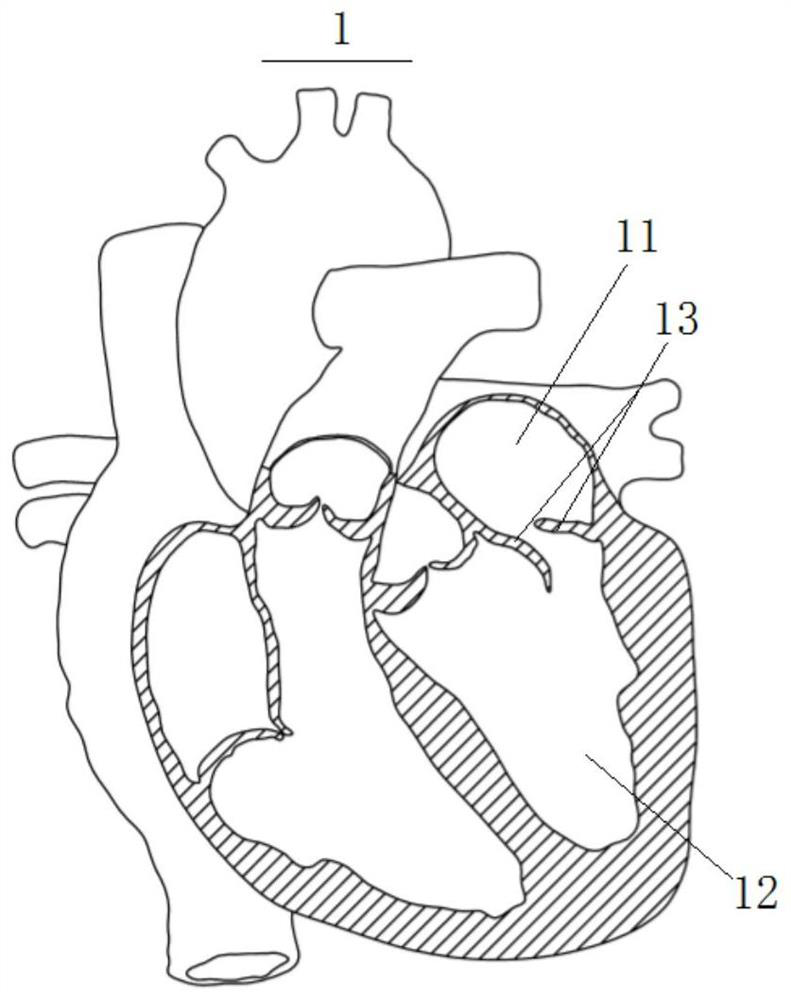
[0060] figure 1 What is shown is a schematic diagram when the mitral valve 13 of the heart 1 has a mitral regurgitation lesion. Usually, the plane where the mitral valve 13 of the heart 1 is located is roughly D-shaped, and there are three main positions where regurgitation is likely to occur, which are respectively defined as the first regurgitation position P1, the second regurgitation position P2 and the third regurgitation position P3. 1 When mitral valve regurgitation occurs, it may be that all three regurgitation sites produce regurgitation lesions, or one or two regurgitation sites produce regurgitation lesions.
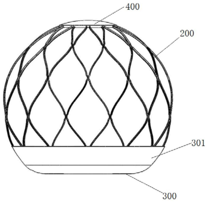
[0061] like Figure 1 to Figure 18 As shown, this embodiment provides a mitral valve regurgitation treatment device, which is used to interfere with the left atrium 11, and includes a stent 200 and a base membrane 300. The stent 200 is an annular grid structure, and the stent 200 is used to contact One end (ie, the bottom end) of the mitral valve 13 has a pl...
Embodiment 2
[0090] In order to increase the area of the through hole 310, to increase the effective valve area of the patient after surgical treatment, and reduce the transvalvular pressure difference, such as Figure 19 ~ Figure 21 As shown, the mitral valve regurgitation treatment device in this embodiment is different from the first embodiment in that the through hole 310 is set as an eccentric circular hole, that is, the base membrane 300 and the through hole 310 are set eccentrically.
[0091] The eccentric circular hole can be set on the side away from the lesion regurgitation position, and then the area of the through hole 310 can be increased to increase the effective valve area and reduce the transvalvular pressure difference. Flow position P1, second reflux position P2, third reflux position P3) The reflux caused by prolapse can be treated by turning the release angle of the device during the release process, specifically as Figure 21 shown. in Figure 21 The a represen...
Embodiment 3
[0096] In order to increase the area of the through hole 310, to increase the effective valve area of the patient after surgical treatment, and reduce the transvalvular pressure difference, such as Figure 22 ~ Figure 24 As shown, the device for treating mitral valve regurgitation in this embodiment is different from Embodiment 1 and Embodiment 2 in that the through hole 310 is set in an oval shape.
[0097] Preferably, the through hole 310 is ellipse eccentric to the base film 300 , and the short side of the ellipse of the through hole 310 is arranged tangent to the edge of the base film 300 .
[0098] The apparatus for treating mitral valve regurgitation in this embodiment is similar to that in Embodiment 2, and the regurgitation caused by prolapse at different positions can be implemented through rotation, specifically as Figure 24 shown. in Figure 24 The a represents the schematic diagram of the treatment when the lesion occurs in the second reflux position P2; F...
PUM
 Abstract
Description
Claims
Application Information
 - R&D
- Intellectual Property
- Life Sciences
- Materials
- Tech Scout
- Unparalleled Data Quality
- Higher Quality Content
- 60% Fewer Hallucinations
Browse by: Latest US Patents, China's latest patents, Technical Efficacy Thesaurus, Application Domain, Technology Topic, Popular Technical Reports.
© 2025 PatSnap. All rights reserved.Legal|Privacy policy|Modern Slavery Act Transparency Statement|Sitemap|About US| Contact US: help@patsnap.com