
Terahertz end-fire array linear array antenna based on dipole antenna unit

A technology of terahertz end-fire array and dipole antenna, which is applied in the direction of antenna array, individually powered antenna array, and specific array feeding system, etc., which can solve the problems of limited output power, complex transmitter structure, and The output power and beam width cannot meet the requirements of high output power, etc., and achieve the effect of high direction coefficient, high beam width, and improved antenna array gain

Pending Publication Date: 2020-12-25
ZHEJIANG NORMAL UNIVERSITY
View PDF0 Cites 0 Cited by
  • Summary
  • Abstract
  • Description
  • Claims
  • Application Information

AI Technical Summary

Problems solved by technology

Space power synthesis linear and planar arrays are generally realized by the method of uniformly changing the phase to excite the antenna array, and the structure of the transmitter is relatively simple; while the phased array generally uses the phase modulator in the transmitter to realize the radio frequency signal of any phase, so as to realize Space angle control of the beam, the transmitter structure is relatively complex
[0003] The existing terahertz transmitter chip system usually uses a side-firing array antenna array to increase the antenna gain, thereby increasing the equivalent isotropic radiated power EIRP of the transmitter, but the output power is still limited; by designing an off-chip silicon-based lens and a dielectric lens, Focusing on terahertz waves can further increase the equivalent isotropic radiated power EIRP, but the output power and beam width of the transmitter chip still cannot meet the high output power requirements for in-depth promotion in consumer electronics and commercial markets.

Method used


Image

  • Terahertz end-fire array linear array antenna based on dipole antenna unit
  • Terahertz end-fire array linear array antenna based on dipole antenna unit
  • Terahertz end-fire array linear array antenna based on dipole antenna unit

Examples


Embodiment Construction

[0035] The present invention will be further explained below in conjunction with the accompanying drawings and embodiments.

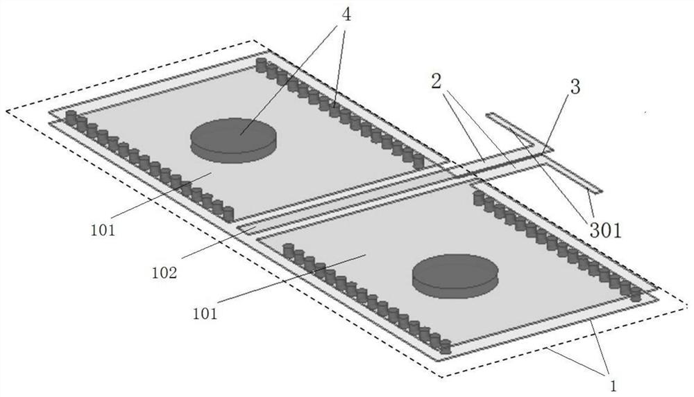
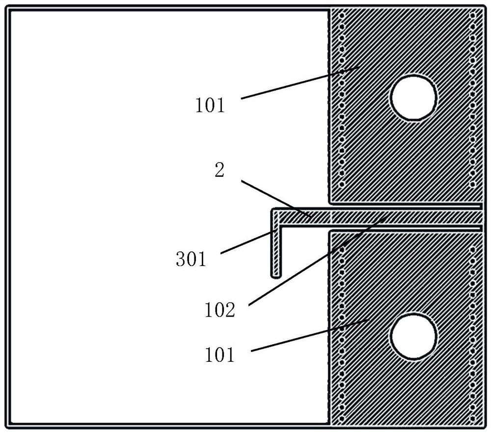
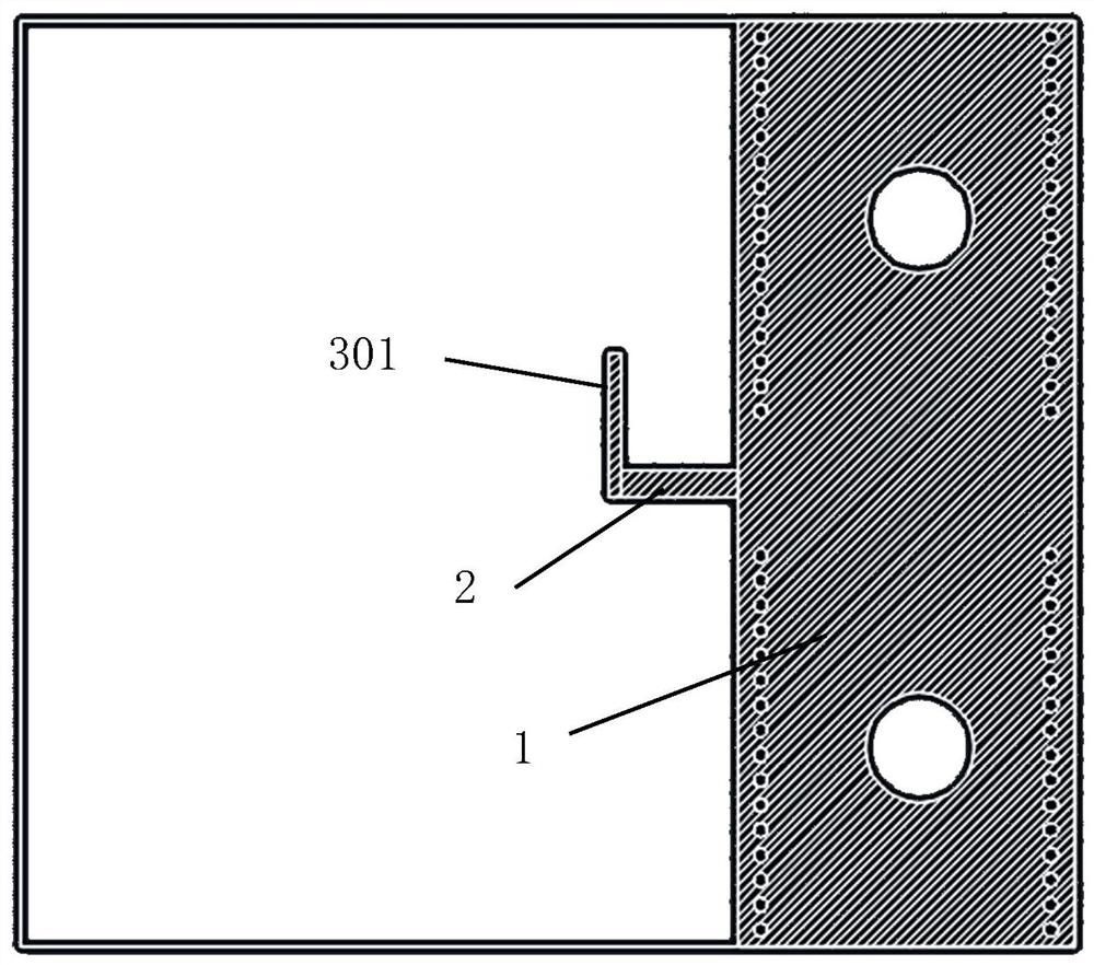
[0036] The end-fire array linear array antenna of the present invention is realized by planar technology, such as PCB technology, SiGe BiCMOS technology or CMOS technology. The PCB process can use the simplest double-panel process to simplify the antenna design. The bottom metal of the lower panel is used as the antenna ground, and the upper metal of the upper panel is used to design the arms of the dipole antenna. The dielectric layer is between the upper metal and the bottom metal. The grounds of the upper panel and the lower panel are connected through metalized via holes. Similarly, for the SiGe BiCMOS process and the CMOS process, the antenna can also be implemented with a double-layer metal.

[0037] A terahertz end-fire array linear array antenna based on a half-wave dipole antenna, the end-fire array linear array antenna uses N dipole antenna e...


PUM


Abstract

The invention belongs to the field of radio frequency circuit design, and particularly relates to a terahertz end-fire array linear array antenna based on a half-wave dipole antenna unit. According tothe end-fire array linear array antenna, N half-wave dipole antenna units (N is greater than or equal to 1) which have N array units and are suitable for a planar process are utilized, and the N*end-fire array linear array antenna suitable for the planar process is constructed by designing the phase difference ([delta]phi=k.pi) of the currents of the adjacent dipole antenna units and the electrical length spacing of the adjacent units, so that the antenna gain and the half-power width of a terahertz transmitter system are improved, and the Terahertz end-fire array linear array antenna is applied to a terahertz transmitter array system with high output power requirements. In addition, in order to enhance the gain of the terahertz end-fire array linear array antenna, M (M is greater than orequal to 1) half-wave dipole antennas can be inserted between the dipole units of which the adjacent half-wavelength electrical lengths are integral multiples.

Description

technical field [0001] The invention belongs to the field of radio frequency circuit design, in particular to a terahertz end-fire linear array antenna based on a half-wave dipole antenna unit. Background technique [0002] For the terahertz transmitter system, the difficulty and focus of research is how to increase the output power of the transmitter. In order to increase the output power, the commonly used transmitter array systems include transmitter phased arrays, transmitter space power combining linear arrays and transmitter space power combining planar arrays. Space power synthesis linear and planar arrays are generally realized by the method of uniformly changing the phase to excite the antenna array, and the structure of the transmitter is relatively simple; while the phased array generally uses the phase modulator in the transmitter to realize the radio frequency signal of any phase, so as to realize The spatial angle control of the beam, the transmitter structure...

Claims


Application Information

Patent Timeline
Patent Type & Authority Applications(China)
IPC IPC(8): H01Q21/00H01Q21/08H01Q1/38H01Q1/50H01Q9/16
CPCH01Q1/38H01Q1/50H01Q9/16H01Q21/0006H01Q21/08
Inventor 毛燕飞鄂世举阚君武
Owner ZHEJIANG NORMAL UNIVERSITY
Learn More