
Pile foundation construction pouring device

A technology of pile foundation and pipe body, applied in the direction of foundation structure engineering, sheet pile wall, manufacturing tools, etc., can solve the problems of prolonged construction period, time consumption, pipe blockage, etc., to save engineering time, reduce engineering time, and prevent engineering accidents. Effect

Active Publication Date: 2020-12-18
浙江兆城建设有限公司
View PDF5 Cites 0 Cited by
  • Summary
  • Abstract
  • Description
  • Claims
  • Application Information

AI Technical Summary

Problems solved by technology

[0003] However, in the existing pile foundation construction, it is necessary to weld the reinforcement cage and put it into the pile hole first, and then pour the concrete, which is very time-consuming and greatly prolongs the construction period; at the same time, it is necessary to place a water blocking plug in the conduit when the pouring is started. It is used to accumulate concrete in the conduit in advance, and the water blocking plug cannot be recovered after pouring; and due to the difference in the diameter of the pile hole during pouring, the rising speed of the concrete is also different. It is necessary to always pay attention to the rising speed of the concrete and measure the immersion depth of the conduit frequently. Accidents are very troublesome; in addition, when concrete is poured, the concrete inside the conduit is easy to accumulate, causing the conduit to block

Method used


Image

  • Pile foundation construction pouring device
  • Pile foundation construction pouring device
  • Pile foundation construction pouring device

Examples


Embodiment Construction

[0033]The technical solutions in the embodiments of the present invention will be clearly and completely described below in conjunction with the accompanying drawings in the embodiments of the present invention. Apparently, the described embodiments are only some, not all, embodiments of the present invention. Based on the embodiments of the present invention, all other embodiments obtained by persons of ordinary skill in the art without making creative efforts belong to the protection scope of the present invention.

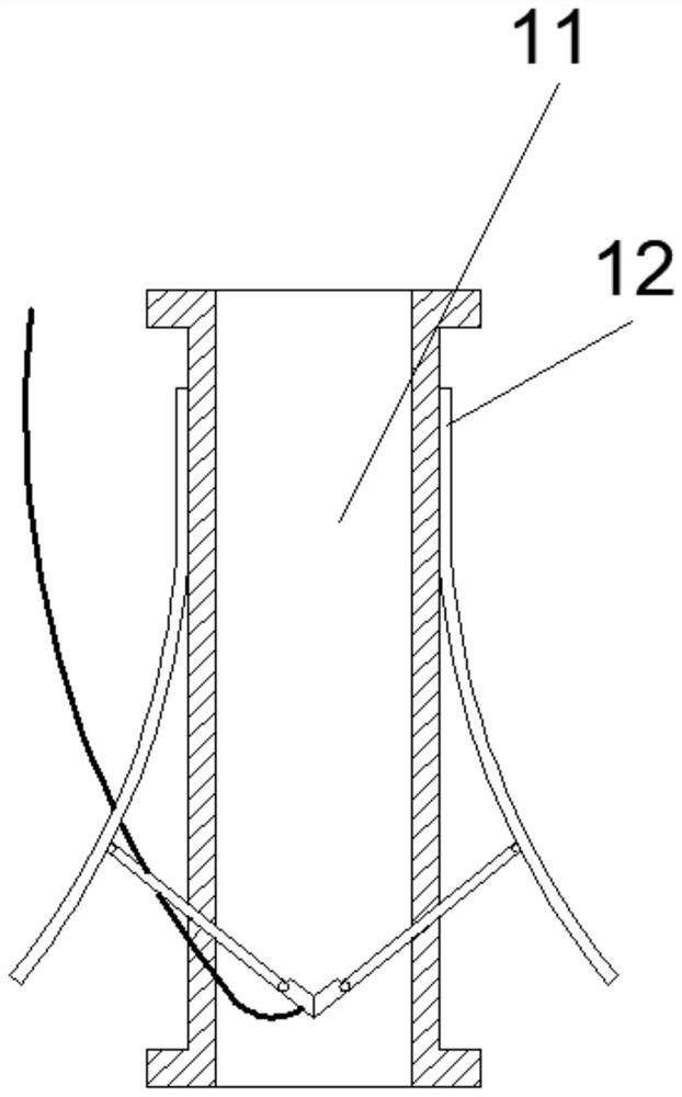
[0034] see Figure 1-9 The present invention provides a technical solution: a pouring device for pile foundation construction, including a water blocking pipe 1, the water blocking pipe 1 includes a water blocking pipe body 11, a plurality of shrapnel 12 are connected to the outside of the water blocking pipe body 11, and shrapnel rollers 1a are installed at the ends of the shrapnel 12, The shrapnel 12 is connected with a movable baffle 13 through a movable bolt...


PUM


Abstract

The invention discloses a pile foundation construction pouring device. The pile foundation construction pouring device comprises a water blocking pipe, wherein a plurality of elastic pieces are connected to the outer side of a water blocking pipe body; the elastic pieces are connected with movable baffles; the movable baffles are connected with movable blocks; a plurality of baffles are arranged between the movable blocks; a plurality of immersion pipes are arranged below the water blocking pipe; a plurality of conveying pipes are arranged above the water blocking pipe; air pipes are clamped in the side face connection of the water blocking pipe, the immersion pipes and the conveying pipes; air bags are arranged at the lower ends of the air pipes; air pressure meters are arranged at the upper ends of the air pipes; vibration rods are arranged in the conveying pipes; conveying rods are arranged on the two sides of the conveying pipe body; steel reinforcement cage conveying arms are arranged on the vibration rod conveying rods; and a steel reinforcement cage rapid connecting device is further included. According to the device, a steel reinforcement cage can be connected and placed during pouring, a water blocking plug does not need to be consumed, the concrete ascending speed can be automatically adjusted, the immersion depth of a guide pipe does not need to be measured, and concrete is not prone to being accumulated in the guide pipe.

Description

technical field [0001] The invention relates to the technical field of construction equipment, in particular to a pouring device for pile foundation construction. Background technique [0002] The foundation composed of piles set in the rock and soil and the cap connected to the top of the pile or the single pile foundation directly connected by columns and piles is called pile foundation. The construction process of organizing and implementing this pile foundation is called pile foundation engineering. In pile foundation construction, pile holes will be formed in the foundation soil by means of mechanical drilling, steel pipe extrusion or manual excavation, and then the prefabricated steel cage will be vertically hung into the hole, fixed after positioning, and finally used Concrete is poured into the conduit to make piles. [0003] However, in the existing pile foundation construction, it is necessary to weld the reinforcement cage and put it into the pile hole first, an...

Claims


Application Information

Patent Timeline
IPC IPC(8): E02D15/04E02D15/08E02D5/34B23K23/00B21F27/12B21F27/10
CPCB21F27/10B21F27/121B23K23/00E02D5/34E02D15/04E02D15/08E02D2250/003
Inventor 林清华陶芹
Owner 浙江兆城建设有限公司
Learn More