Slender shaft numerical control lathe fixture

A technology of CNC lathes and slender shafts, applied in the directions of clamping, clamping devices, manufacturing tools, etc., can solve problems such as machining errors of slender shafts, and achieve the effects of improving turning accuracy, good use effect, and simple structure

Inactive Publication Date: 2020-12-08
杨兰
View PDF0 Cites 0 Cited by
  • Summary
  • Abstract
  • Description
  • Claims
  • Application Information

AI Technical Summary

Problems solved by technology

However, this method requires multiple clamping of the slender shaft, resulting in machining errors of the slender shaft
[0004] Design a slender shaft CNC lathe fixture to solve the problems in traditional slender shaft machining

Method used


Image

  • Slender shaft numerical control lathe fixture
  • Slender shaft numerical control lathe fixture
  • Slender shaft numerical control lathe fixture

Examples


Embodiment Construction

[0038] The accompanying drawings are all schematic diagrams of the implementation of the present invention, so as to understand the principle of structural operation. The specific product structure and proportional size can be determined according to the use environment and conventional technology.

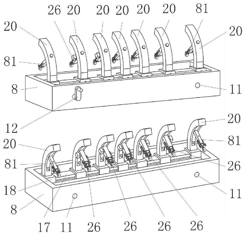
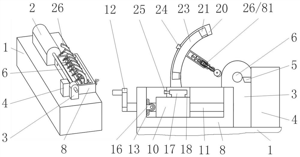
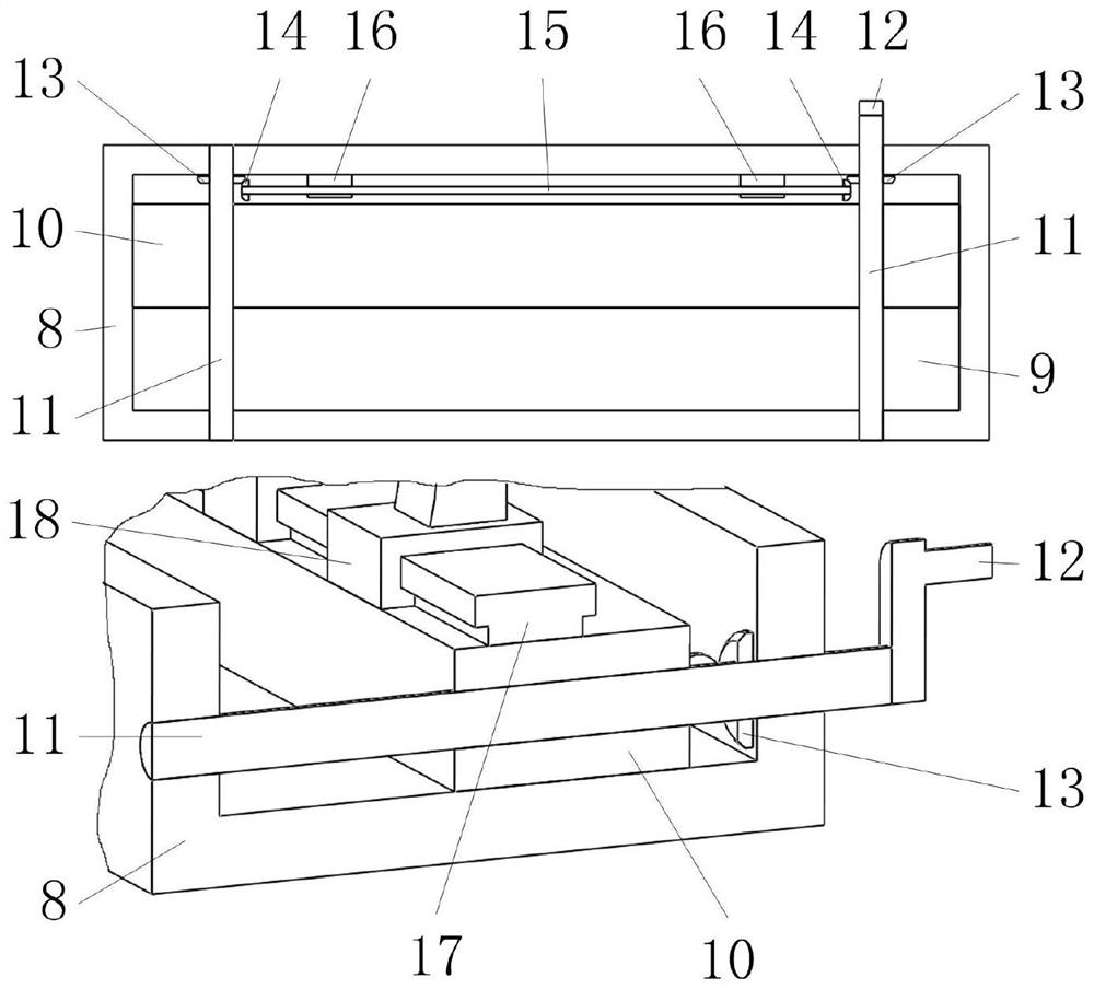
[0039] Such as figure 1 , 3 As shown, it includes a base 8, a sliding seat 10, a screw A11, an arc bracket 20, a T-shaped guide block 23, a telescopic rod structure A26, and a telescopic rod mechanism B81, among which figure 2 , 3 As shown, the sliding seat 10 slides in the chute A9 on the base 8 along the axial direction perpendicular to the slender shaft 6, and the base 8 is installed on the bed of the machine tool; as figure 1 , 2 As shown, a number of arc-shaped brackets 20 distributed along the axial direction of the elongated shaft 6 slide on the sliding seat 10 along the axial direction of the elongated shaft 6, and the concave arc surface of the arc-shaped brackets 20...


PUM


Abstract

The invention belongs to the field of numerical control lathe fixtures, and particularly relates to a slender shaft numerical control lathe fixture. The slender shaft numerical control lathe fixture comprises a base, a sliding seat, a screw rod A, an arc-shaped support, a T-shaped guide block, a telescopic rod structure A and a telescopic rod mechanism B, wherein the sliding seat slides in a sliding groove A in the base in the direction perpendicular to the axial direction of a slender shaft; and the base is mounted on a lathe body. According to the slender shaft numerical control lathe fixture, the plurality of telescopic rod mechanisms A staggered at a certain angle wrap the slender shaft at a certain angle while effectively abutting against the slender shaft in the turning process, so that vibration caused by lower strength of the slender shaft in the rotating process is avoided, and the turning precision of the slender shaft is improved.

Description

technical field [0001] The invention belongs to the field of fixtures for numerically controlled lathes, in particular to a fixture for numerically controlled lathes with slender shafts. Background technique [0002] A shaft with a ratio of length to diameter greater than 25 (ie L / D>25) is called a slender shaft. Due to the poor rigidity of the slender shaft and the action and influence of cutting force, cutting heat and vibration during turning, it is easy to deform, and there are processing errors such as straightness and cylindricity, and it is difficult to achieve the shape and position accuracy and surface of the pattern. Quality and other technical requirements make cutting very difficult. The larger the L / d value, the more difficult the turning process. The rigidity of the slender shaft is poor. Due to the influence of many factors such as the machine tool and the cutting tool during the processing, the workpiece is prone to defects such as bending waist drum sha...

Claims


Application Information

Patent Timeline
IPC IPC(8): B23Q3/00
CPCB23Q3/00B23Q2703/10
Inventor 杨兰
Owner 杨兰
Why Eureka
Try Eureka