Non-round cutting device of digital control lathes and control method thereof

A technology of CNC lathes and cutting devices, which is applied in the direction of digital control, turning equipment, turning equipment, etc., can solve the problems of high processing cost, poor processing accuracy, and low efficiency, and achieve the effect of protecting from damage and improving turning accuracy

Inactive Publication Date: 2010-01-13
NINGBO UNIV
View PDF4 Cites 0 Cited by
  • Summary
  • Abstract
  • Description
  • Claims
  • Application Information

AI Technical Summary

Problems solved by technology

The profiling processing method uses the profiling to control the relative motion trajectory of the tool and the workpiece to form the required surface shape. This method has a wide range of processing and can process workpieces with complex cross-sectional shapes, but the efficiency is low, the adjustment is complicated and the processing accuracy is poor; Special processing can be used for the finishing of non-circular parts, but the processing cost is high and the efficiency is low, and it is difficult to process workpieces with complex cross-section and shaft cross-section shapes; the processing principle of CNC turning is: in the non-circular cross-section During the machining process, the tool tracks the rotation angle of the spindle in the X direction (horizontal direction), adjusts the tool position in real time, and realizes the reciprocating movement of the tool in the X-axis direction, thereby processing the required non-circular line. However, the X-axis of the current CNC system The response frequency cannot meet the requirements of high-speed reciprocating motion, and the precision of turning processing is not ideal.

Method used


Image

  • Non-round cutting device of digital control lathes and control method thereof
  • Non-round cutting device of digital control lathes and control method thereof
  • Non-round cutting device of digital control lathes and control method thereof

Examples


Embodiment 1

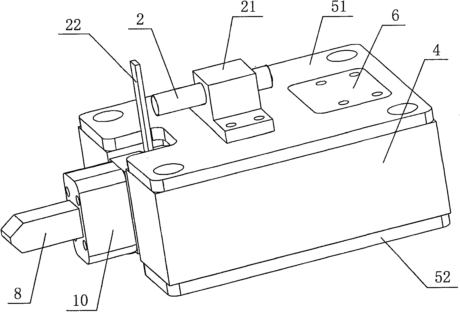
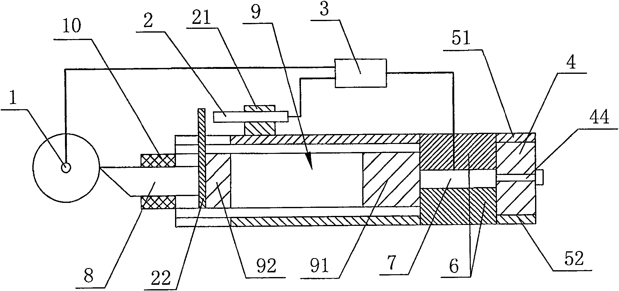
[0020] Embodiment 1: As shown in the figure, a non-circular cutting device of a CNC lathe, including a tool holder 4, a tool holder 10 with a tool 8 fixed thereon, a high-precision displacement sensor 2, a high-precision rotary encoder 1, and a piezoelectric ceramic actuator The controller 7 and the controller 3, the high-precision rotary encoder 1 and the high-precision displacement sensor 2 are electrically connected to the controller 3, the controller 3 is electrically connected to the piezoelectric ceramic actuator 7, and the high-precision rotary encoder 1 is set on the CNC lathe On the spindle motor of the tool rest 4, the upper surface of the tool rest 4 is fixedly provided with an upper cover plate 51, the lower surface of the tool rest 4 is fixedly provided with a lower cover plate 52, and the tool rest 4 is provided with a first cavity 41 and a second cavity connected to each other. Cavity 42, flexible hinge structure 9 is arranged in the first cavity 41, and flexible...

Embodiment 2

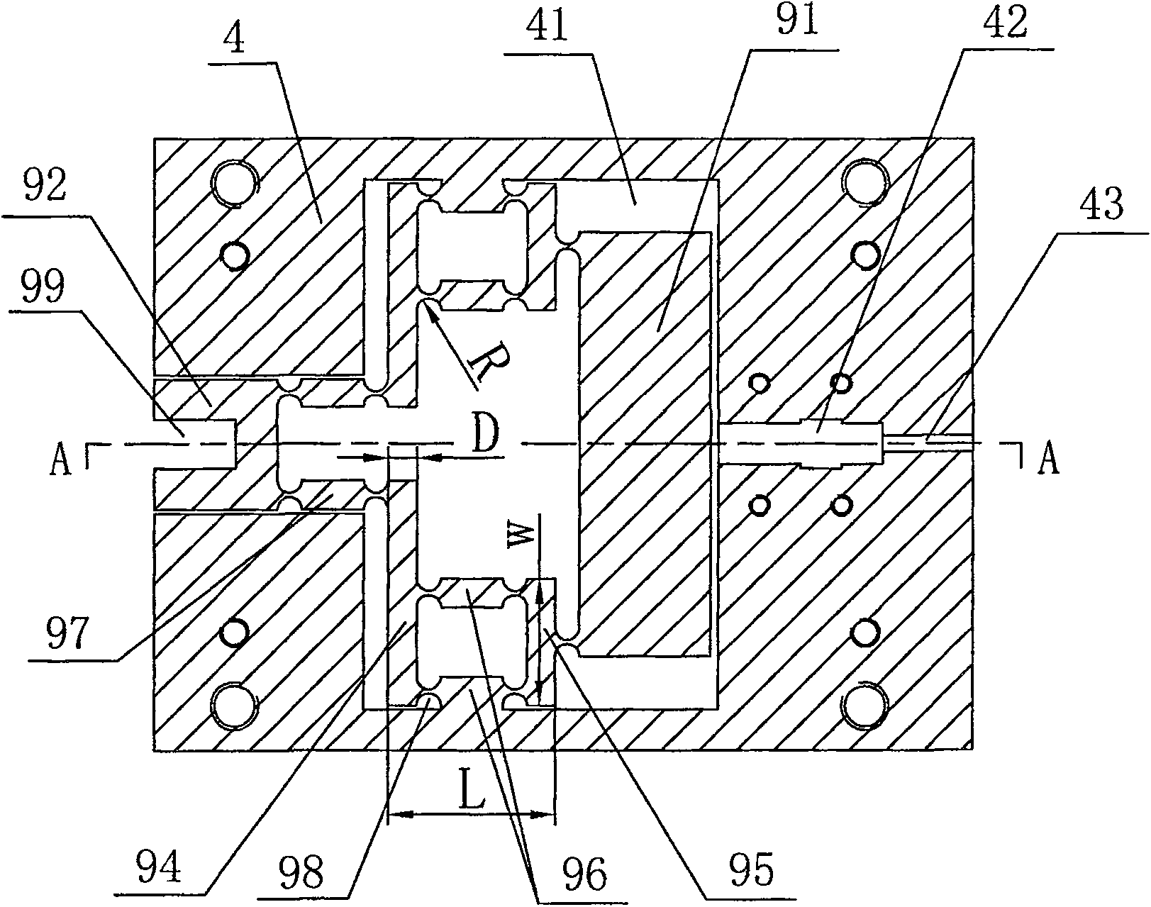
[0025] Embodiment two: other structures are the same as embodiment one, the difference is that in the parallelogram elastic mechanism, the radius R of the semicircular groove 98 is 3mm, the first connecting rod 94, the second connecting rod 95, the third connecting rod 96, the fourth connecting rod The width D of the four connecting rods 97 is 7mm, the height H is 30mm, the distance L from the first connecting rod 94 to the second connecting rod 95 is 40mm, and the distance W between the two third connecting rods 96 is 30mm .

Embodiment 3

[0026] Embodiment three: other structures are the same as embodiment one, the difference is that in the parallelogram elastic mechanism, the radius R of the semicircular groove 98 is 3.5mm, the first connecting rod 94, the second connecting rod 95, the third connecting rod 96, the first connecting rod The width D of the four connecting rods 97 is 8mm, the height H is 32mm, the distance L from the first connecting rod 94 to the second connecting rod 95 is 40mm, and the distance W between the two third connecting rods 96 is 30mm.


PUM

PropertyMeasurementUnit
radiusaaaaaaaaaa

Abstract

The invention discloses a non-circular cutting device for a numerically controlled lathe, which comprises a cutter head, a cutter holder fixed with cutters, a displacement sensor, a main shaft coder, an actuator, and a controller, wherein the main shaft coder is arranged on a main shaft motor of the numerically controlled lathe. The non-circular cutting device is characterized in that the cutter head is provided with a first cavity and a second cavity which are communicated with each other, a flexible hinge structure is arranged in the first cavity integrally, the front end part of the flexible hinge structure is integrally provided with a permanent seat of the cutter holder, the cutter holder is fixedly arranged on the permanent seat of the cutter holder, the actuator is fixedly arranged in the second cavity, the end part of the actuator leans against the rear end face of the flexible hinge structure, the main shaft coder and the displacement sensor are both electrically connected with the controller, and the controller is electrically connected with the actuator. The non-circular cutting device has the advantages that the cutter head has the functions of micro positioning and precision cutting vibration control to realize micro feeding movements of the cutters in a non-circular precise cutting system, the cutting vibration in axial and tangential directions of a workpiece can be controlled effectively, and the turning precision of non-circular cutting is improved.

Description

technical field [0001] The invention relates to a cutting device of a numerically controlled lathe, in particular to a non-circular cutting device of turning equipment and a control method thereof. Background technique [0002] According to the rotation cycle of the main shaft, the displacement of the tool in the radial direction (lateral direction) of the workpiece can be controlled synchronously, and the workpiece with a non-circular cross-section shape can be processed. This processing method is called non-circular cross-section turning. At present, the methods for processing non-circular cross-sectional contours mainly include: profiling, special processing and CNC turning. The profiling processing method uses the profiling to control the relative motion trajectory of the tool and the workpiece to form the required surface shape. This method has a wide range of processing and can process workpieces with complex cross-sectional shapes, but the efficiency is low, the adjus...

Claims


Application Information

Patent Timeline
Patent Type & Authority Patents(China)
IPC IPC(8): B23B5/36B23B21/00G05B19/18G05B13/02
Inventor 李国平韩同鹏沈杰邹翔
Owner NINGBO UNIV
Why Eureka
Try Eureka