
Compound vibrated ultrasonic bone surgery apparatus

A surgical instrument and bone technology, applied in the field of ultrasonic bone surgical instruments, can solve the problems of thermal injury of nerves and blood vessels in the accessories of cutting wounds, increased temperature of the cutting wound surface, low efficiency of cutting bones, etc., to achieve good protection, improve The effect of operation safety and precision, and fewer complications

Active Publication Date: 2006-02-15
北京速迈医疗科技有限公司
View PDF7 Cites 44 Cited by
  • Summary
  • Abstract
  • Description
  • Claims
  • Application Information

AI Technical Summary

Problems solved by technology

In this way, the surgical knife can only vibrate back and forth in the longitudinal direction, and the efficiency of cutting bone is low, and the friction between the surgical knife and the wound surface is relatively large, which will easily cause the temperature of the cutting wound surface to rise, and even cause the cutting wound to become thinner. Thermal injury to adjacent nerves and blood vessels
[0007] In addition, the shape of the surgical knife of the existing ultrasonic surgical instrument generally transitions from the thicker end installed on the horn to the thinner end for cutting, so that the cutting stress is mainly concentrated at the end of the transition , so that the part is prone to fatigue fracture, resulting in damage to the surgical tool

Method used


Image

  • Compound vibrated ultrasonic bone surgery apparatus
  • Compound vibrated ultrasonic bone surgery apparatus
  • Compound vibrated ultrasonic bone surgery apparatus

Examples


Embodiment Construction

[0035] Embodiments of the invention will now be described in detail, examples of which are illustrated in the accompanying drawings, in which like reference numerals refer to like parts.

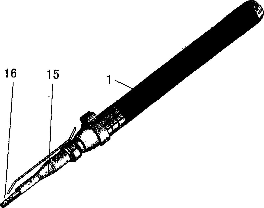
[0036] figure 2 It is a three-dimensional schematic diagram of the handle of the composite vibration ultrasonic bone surgery instrument of the present invention, image 3 yes figure 2 Longitudinal cross-sectional view of the handle of the ultrasonic bone surgical instrument with compound vibration shown. refer to figure 2 and 3, the composite vibration ultrasonic bone surgery instrument includes a handle 1, a scalpel 16 installed at the front end of the handle 1, and an ultrasonic signal generator, wherein the shell 2 of the handle 1 includes: a transducer 9, a horn 10, and a drive motor 4 and adapters. The transducer 9 converts the ultrasonic signal sent by the ultrasonic signal generator into an ultrasonic mechanical wave, and the horn 10 amplifies the amplitude of the ultrasonic m...


PUM


Abstract

A compound vibrating supersonic bone surgery instrument, including handle, operating knife and main machine, and inside the shell of the handle includes: transfer the signal emitted by supersonic signal generator to supersonic mechanical waves of energy converter, deliver the supersonic mechanical waves emitted by energy converter after amplitude magnification to amplitude changing pole of surgery knife to make the surgery knife vibrate longitudinally at supersonic frequency; install in the back end of the handle, and the energy converter and amplitude changing pole are rotated or swayed by driving motor; install on the clutch between the said driving motor and energy converter to deliver the supersonic signal emitted by supersonic signal generator to electric slip-ring of energy converter; cross the center bore of electric slip-ring and deliver the rotating and swaying movement of driving motor to the clutch of energy converter. The invention installs driving motor at the base of the energy converter, accomplishing compound supersonic vibration; accomplishing cold cutting; avoiding the broken of surgery knives as a result of the concentration of stress.

Description

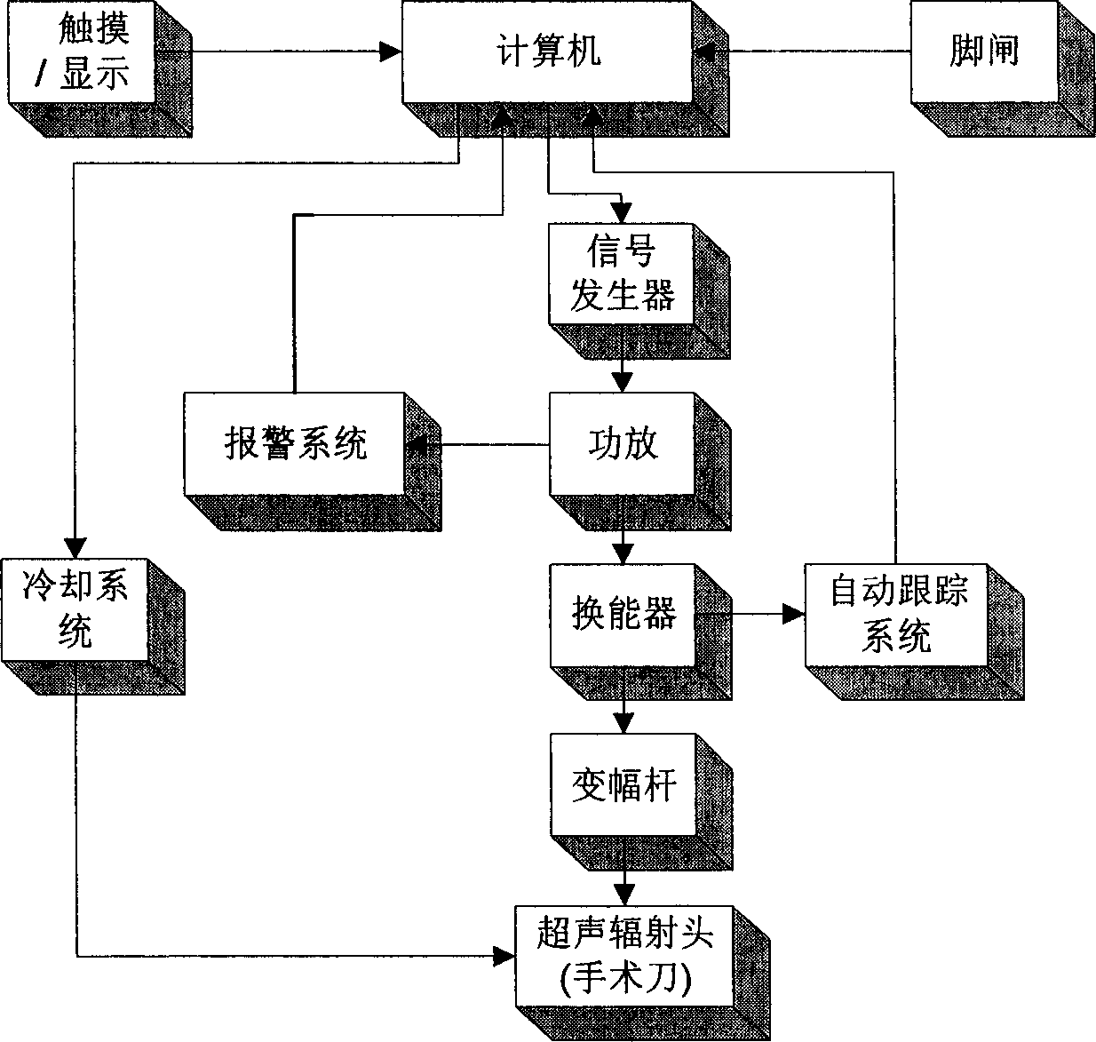
technical field [0001] The invention relates to a surgical medical device, more specifically, to an ultrasonic bone surgical instrument whose ultrasonic surgical tool can vibrate both longitudinally and rotatably. Background technique [0002] With the rapid development of modern medicine, ultrasonic surgical instruments have been more and more used in clinical surgical treatment. It applies ultrasonic energy to surgical operations. Its outstanding features are fine cutting, safety, tissue selectivity and low temperature hemostasis. etc., have greatly enriched the means of surgical operations, improved the quality of surgical operations, and alleviated the pain of patients to a certain extent. figure 1 It is the system working principle diagram of the conventional ultrasonic bone surgery instrument. The system is mainly composed of a host, a handle, a knife and a foot switch. The host mainly includes an ultrasonic signal generator, a power amplifier and an embedded computer...

Claims


Application Information

Patent Timeline
Patent Type & Authority Applications(China)
IPC IPC(8): A61B17/32A61B17/00
CPCA61B17/32002A61B2017/320084A61B17/320068A61B2017/32007A61B2017/320082
Inventor 周兆英史文勇张毓笠罗晓宁
Owner 北京速迈医疗科技有限公司
Learn More