Numerical control turning machining center

A machining center and turning technology, which is applied in the field of turning processing, can solve the problems of cutter deviation and damage, reduce the processing efficiency of equipment, and cannot accurately cut the knife, etc., and achieve the effect of improving machining accuracy and efficiency

Inactive Publication Date: 2020-12-18
卢锦锋
View PDF0 Cites 0 Cited by
  • Summary
  • Abstract
  • Description
  • Claims
  • Application Information

AI Technical Summary

Problems solved by technology

[0004] The main purpose of the present invention is to overcome the deficiencies of the prior art and provide a numerically controlled turning machining center to solve the problem of error-prone data detection when processing special-shaped m...

Method used


Image

  • Numerical control turning machining center
  • Numerical control turning machining center
  • Numerical control turning machining center

Examples


Embodiment 1

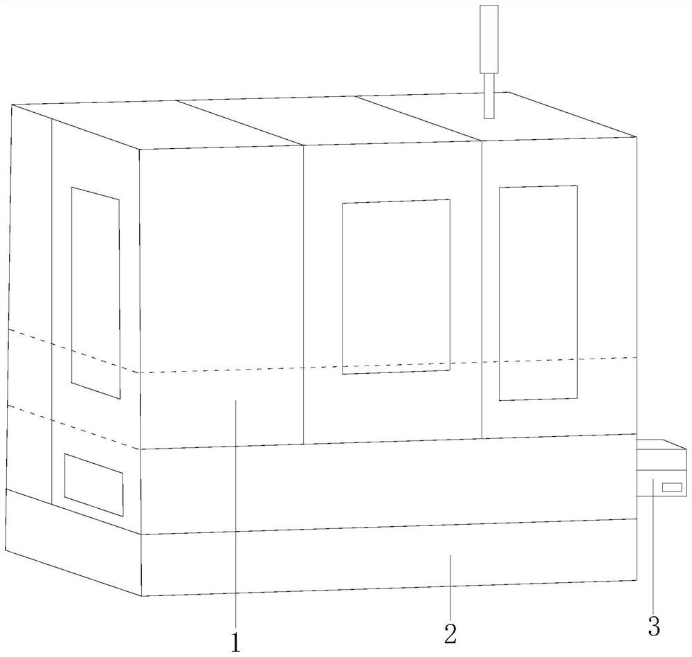
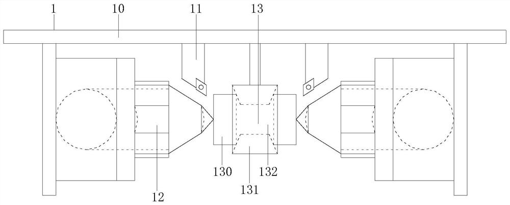
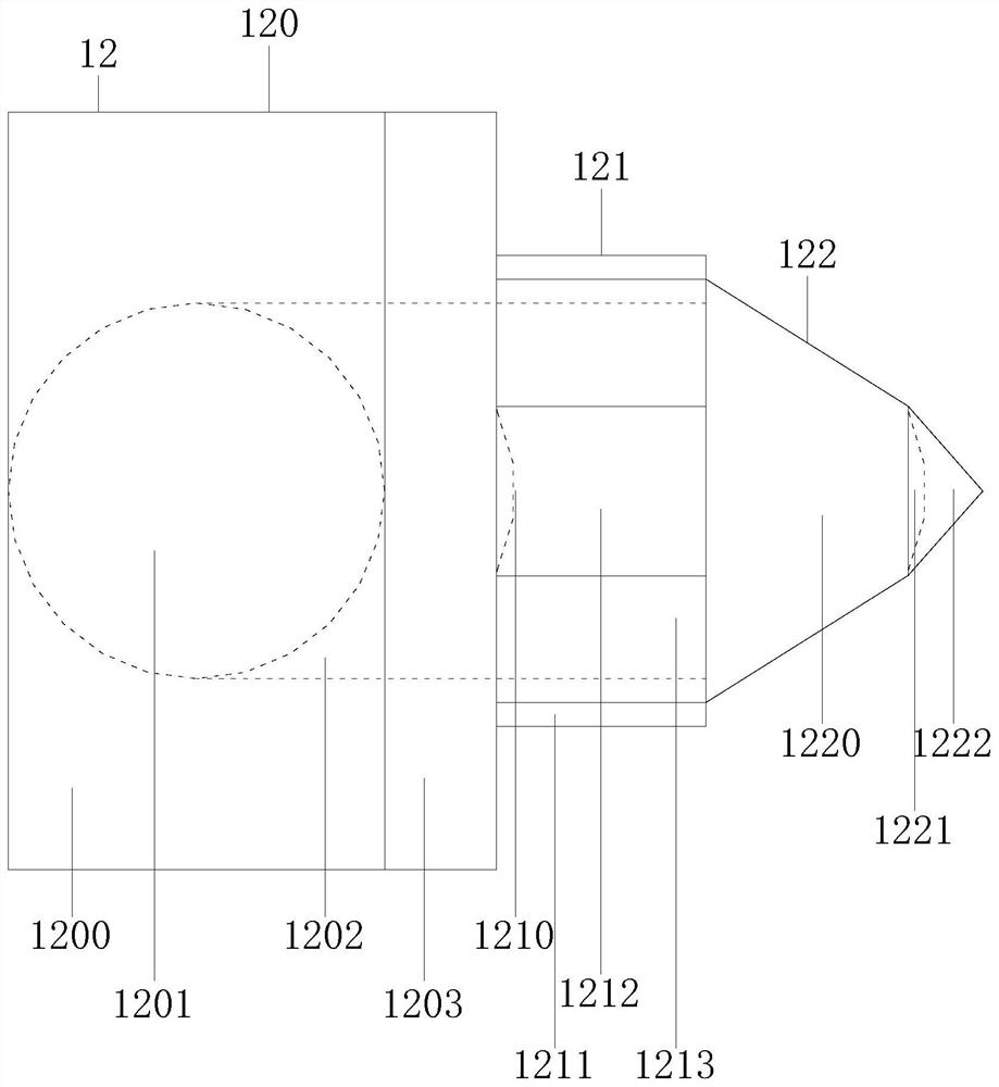
[0024] Example 1 see Figure 1-3 , the present invention provides a technical solution for a numerical control turning machining center: its structure includes a turning device 1, a turning machine 2, and a console 3, the turning device 1 is installed on the turning machine 2, and the turning machine 2 is locked with the console 3 And the two are electrically connected, the turning device 1 is composed of a mounting frame 10, a turning knife 11, a side end feeding device 12, and a middle part feeding device 13, the mounting frame 10 is connected to the turning blade 11, and the mounting frame 10 is locked with the side end material fixing device 12 and the middle part material fixing device 13, and the side end material fixing device 12 fixes the materials located at both ends of the middle part material fixing device 13, and the middle part material fixing device 13 includes material level 130, internal setting device 131 and middle pile 132, the material level 130 is install...

Embodiment 2

[0026] Example 2 see Figure 4 , 5 , the present invention provides a technical solution for a numerical control turning machining center: the internal fixer 131 includes an internal fixed frame structure 1310 and an internal fixed movable structure 1311, and the internal fixed movable structure 1311 adjusts the movement of materials and strengthens the fixing of materials. The internal fixed frame structure 1310 is installed and connected with the internally fixed movable structure 1311. The internally fixed frame structure 1310 includes a fixed structure frame 41 and a device shaft 42. The fixed structure frame 41 is connected to the device shaft 42. Block 50, middle fixed block 51, movable fixed material rack 52, inner fixed device shaft 53, described movable fixed block 50 is connected with middle fixed block 51 tracks, and described movable fixed block 50 comprises fixed material arc frame 500, arc frame track 501 , the fixed material arc frame 500 is connected with the ...


PUM


Abstract

The invention discloses a numerical control turning machining center. The numerical control turning machining center structurally comprises a turning device, a turning machine and a control console, the turning device is installed on the turning machine, the turning machine and the control console are locked and electrically connected, the turning device is composed of an installation frame, a turning cutter, a side end material fixing device and a middle material fixing device, the installation frame is connected with the turning cutter, the installation frame is locked with the side end material fixing device and the middle material fixing device, the middle material fixing device comprises a material position, an inner fixer and a middle pile, the material position is mounted on the middle pile, the inner fixer is connected with the middle pile in an installed mode, the side end material fixing device comprises a main adjusting structure, an auxiliary adjusting structure and a conical fixing structure, and the auxiliary adjusting structure is connected with the main adjusting structure and the conical fixing structure in an installed mode. According to the numerical control turning machining center, raw materials are located at the material position and are moved and adjusted through the side end material fixing device and the middle material fixing device, meanwhile, turning machining is carried out through the turning cutter, and turning machining is carried out by replacing turning cutter path movement with material moving, so that the machining precision and efficiency are improved.

Description

technical field [0001] The invention relates to the field of turning processing, in particular to a numerically controlled turning processing center. Background technique [0002] Turning processing route refers to the path that the turning tool moves from the tool setting point until it returns to this point and ends the processing program. The processing route is the shortest during processing, which reduces the idle travel time and simplifies the processing program. [0003] In the existing technology, when processing special-shaped materials, data detection is prone to errors, which will lead to repeated routes or deviations at corners or micro-defects, making it impossible to accurately cut the knife, and the cutter is easily damaged due to deviation, which reduces the processing efficiency of the equipment. Contents of the invention [0004] The main purpose of the present invention is to overcome the deficiencies of the prior art and provide a CNC turning machining ...

Claims


Application Information

Patent Timeline
IPC IPC(8): B23B7/00B23B23/00
CPCB23B7/00B23B23/00
Inventor 卢锦锋
Owner 卢锦锋
Why Eureka
Try Eureka