
Laser ablation method and device

A laser ablation, laser technology, used in measuring devices, laser welding equipment, instruments, etc., can solve problems such as host mineral interference, and achieve the effect of high-precision analysis

Active Publication Date: 2020-12-04
INST OF GEOCHEM CHINESE ACADEMY OF SCI
View PDF6 Cites 2 Cited by
  • Summary
  • Abstract
  • Description
  • Claims
  • Application Information

AI Technical Summary

Problems solved by technology

[0004] Therefore, the technical problem to be solved by the present invention is that the existing laser ablation system can only carry out gradual ablation from the surface to the inside, and will be interfered by host minerals, thereby providing a laser ablation method and its device

Method used


Image

  • Laser ablation method and device
  • Laser ablation method and device
  • Laser ablation method and device

Examples


Embodiment 1

[0047] This embodiment provides a laser ablation method, comprising the following steps:

[0048] S1, clean the sample to be tested, determine the position to be ablated, and then put it into the sample pool;

[0049] S2, using a nonlinear laser to ablate the sample, and the nonlinear laser focuses on the inside of the sample, and performs fixed-point focusing and blasting inside the sample.

[0050] Among them, the laser optical path is adjusted according to different samples. When performing ablation, the nonlinear laser pulse width is <1ns, the wavelength is <1100nm, the frequency is 1-50000Hz, the power is 0-15W, the ablation depth of the sample is 1-20μm, and the ablation time 5~40s.

[0051]S3, the whole course of the erosion process is observed through the camera and / or the eyepiece, and at the same time, the erosion signal can be collected through equipment such as an inductively coupled plasma mass spectrometer, and the erosion process and results can be analyzed.

...

Embodiment 2

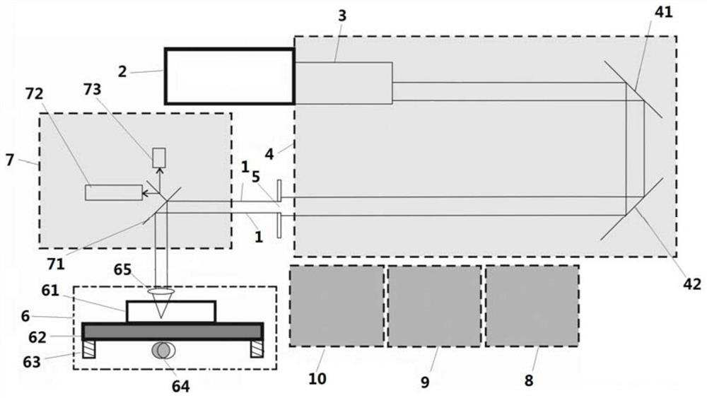
[0054] The invention provides a nonlinear laser ablation device, such as figure 1 As shown, a nonlinear laser 2 is used as the laser source.

[0055] The laser ablation device includes a laser emitting assembly, an optical path system 4, an observation system 7, and an ablation pool 6. The nonlinear laser 1 emitted by the laser emitting assembly enters the ablation pool 6 after being adjusted by the optical path system 4, and the inside of the ablation pool 6 Laser ablation is performed on the sample, and then the sample in the ablation pool 6 is observed through the observation system 7 to observe the state of laser ablation.

[0056] Wherein, the laser emitting component includes a nonlinear laser 2 and an energy adjuster 3 for adjusting the energy of the nonlinear laser, and the energy adjuster 3 is arranged on one side of the nonlinear laser 2 . The nonlinear laser 2 can emit a nonlinear laser 1 , which generally can be a femtosecond laser or a picosecond laser, and the n...

Embodiment 3

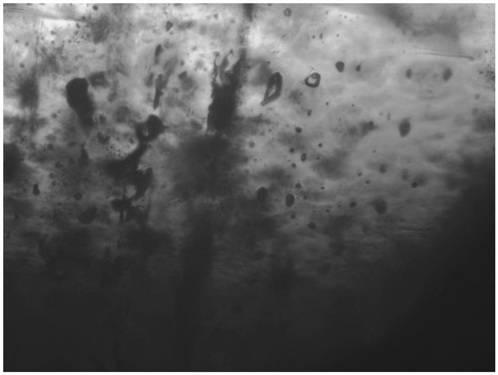
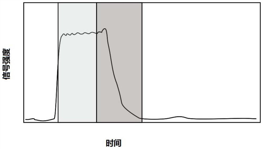
[0075] In this example, the non-linear laser ablation device in Example 2 is used, and the ablation method in Example 1 is used to ablate the fluid inclusions in the sphalerite sample, as shown in the photo figure 2 As shown, the elemental signal diagram collected by inductively coupled plasma mass spectrometry when the sample is stripped is as follows image 3 shown.


PUM


Abstract

The invention discloses a laser ablation method. Nonlinear lasers are adopted to carry out ablation on a sample. The invention further discloses a laser ablation device adopting the laser ablation method. The laser ablation device comprises a laser emitting assembly used for emitting nonlinear lasers, a light path system allowing the nonlinear lasers to penetrate and an ablation pool used for carrying out ablation on the sample through the nonlinear lasers. According to the method and the device, a nonlinear laser device is used as a laser source, self-focusing of the nonlinear lasers is utilized, the great power density is achieved at the focal point, and therefore the laser energy is concentrated in the sample at a specific depth. Nonlinear laser ablation is adopted as the basis, the influence of host mineral ablation on fluid inclusion analysis is reduced to the maximum extent, and high-precision analysis of fluid inclusion components is realized.

Description

technical field [0001] The invention relates to the field of laser ablation analysis, in particular to a laser ablation method and a device thereof. Background technique [0002] Laser ablation-inductively coupled plasma mass spectrometry (LA-ICP-MS) can achieve micron-scale element-isotope measurement and high-precision in-situ determination of geological age, so it has become the most commonly used and most popular method in solid earth science research today. One of the cutting-edge analytical techniques. For the laser ablation-inductively coupled plasma mass spectrometry method, the principle is to use a laser generator to generate high-energy laser to act on the surface of geological samples to decompose the geological samples into fine particles, and then use carrier gas (such as helium) to remove the ablation particles to The aerosol form is transported to an inductively coupled plasma mass spectrometer, and the aerosol is ionized into ions by high-temperature plasma...

Claims


Application Information

Patent Timeline
Patent Type & Authority Applications(China)
IPC IPC(8): B23K26/36B23K26/03B23K26/064B23K26/14B23K26/70G01N27/62
CPCB23K26/032B23K26/14B23K26/36B23K26/064B23K26/702G01N27/626
Inventor 高剑峰
Owner INST OF GEOCHEM CHINESE ACADEMY OF SCI
Learn More