
Tool state image classification method based on edge mark graph neural network

A neural network and classification method technology, applied in the field of tool state image classification, can solve problems such as difficulties, non-stationary tool signals, and inability to make full use of state information

Pending Publication Date: 2020-12-01
WENZHOU UNIVERSITY
View PDF0 Cites 8 Cited by
  • Summary
  • Abstract
  • Description
  • Claims
  • Application Information

AI Technical Summary

Problems solved by technology

However, these methods all need certain preconditions to achieve ideal results. For example, the fast Fourier transform (FFT) requires the signal to be stationary, while the tool signal is non-stationary in the process of machine tool processing; although the wavelet transform (WT) It can deal with non-stationary signals, but it needs to construct and select a wavelet basis function that matches the fault characteristic waveform and has excellent properties
For the tool damage process of machine tool with little prior knowledge, it is very difficult to choose the appropriate wavelet basis function; the artificial neural network (ANN) algorithm needs a large number of sample data for training, which is very difficult for tool condition monitoring
In the case of limited samples, the artificial neural network (ANN) is prone to overfitting problems, that is, the generalization ability is poor; the hidden Markov chain (HMM) method assumes that the state duration obeys an exponential distribution, and the tool damage process is difficult to satisfy This condition; Support Vector Machine (SVM) shows good classification performance in the case of small samples, but it can only identify according to the signal characteristics at the current moment, and cannot make full use of the state information before and after the signal. Time-varying tool damage processes have limitations

Method used


Image

  • Tool state image classification method based on edge mark graph neural network
  • Tool state image classification method based on edge mark graph neural network
  • Tool state image classification method based on edge mark graph neural network

Examples


Embodiment Construction

[0039] In order to make the object, technical solution and advantages of the present invention clearer, the present invention will be further described in detail below in conjunction with the accompanying drawings.

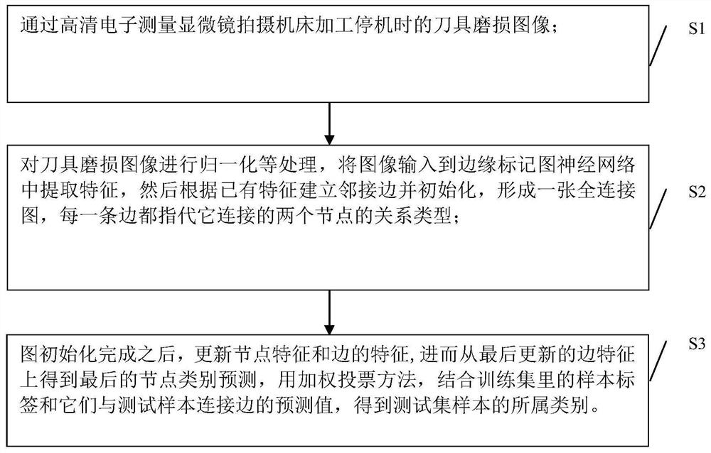
[0040] Such as figure 1 As shown, in the embodiment of the present invention, the following steps are included:

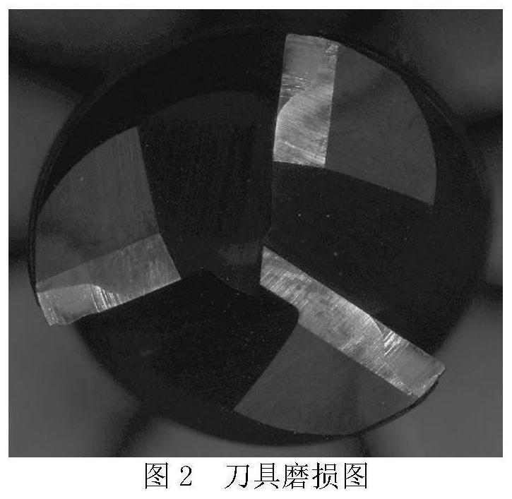
[0041] (1) Arrange and adjust the lighting system, set the magnification ratio of the lens, adjust the position of the tool to be tested, and then use a high-definition electronic measurement microscope to capture the tool wear image when the machine tool is shut down. The tool wear diagram is shown below:

[0042] (2) All the tool wear images captured in the experiment are divided into initial wear, normal wear, and sharp wear according to the size of the wear area.

[0043] (3) The pixels of the original image are large and there are many useless backgrounds, and preprocessing such as image cropping is performed. Then perform data normalization an...


PUM


Abstract

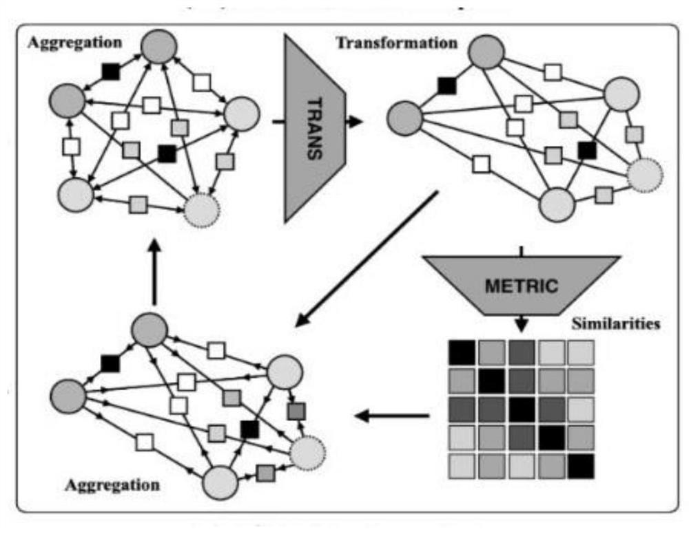
The invention discloses a cutter state image classification method based on an edge mark graph neural network. The method comprises the steps that S1, a high-definition electronic measurement microscope is used for shooting a cutter abrasion image when a machine tool is shut down during machining; s2, normalization and other processing are carried out on the cutter abrasion image, the image is input into an edge mark graph neural network to extract features, then adjacent edges are established according to the existing features and initialized, a full connection graph is formed, and each edgerefers to the relation type of two nodes connected with the edge; and S3, after the graph initialization is completed, updating the node features and the edge features, further obtaining the final node category prediction from the finally updated edge features, and obtaining the category to which the test set sample belongs by using a weighted voting method in combination with the sample labels inthe training set and the prediction values of the connecting edges of the sample labels and the test sample. The method has the advantage that the wear state of the cutter can be well recognized under the condition of small sample images.

Description

technical field [0001] The invention relates to a method for classifying tool state images, in particular to a method for classifying tool state images based on an edge label graph neural network. Background technique [0002] With the advent of Industry 4.0, manufacturing enterprises have higher and higher demands for intelligent production processes, and the automation of CNC machine tools is an important part of the intelligentization of most manufacturing processes. As the most easily damaged part of CNC machine tools in machining, cutting tools are very important for real-time and effective fault identification and status monitoring. The main reasons are: (1) According to statistics, in cutting processing, tool failures usually account for about 20% of the time, and frequent shutdowns and tool changes seriously affect the production efficiency of the enterprise; (2) If the tool breaks down and is not found in time, it will directly affect the surface quality and dimensi...

Claims


Application Information

Patent Timeline
IPC IPC(8): G06T7/13G06T7/11G06T7/00G06N3/04G06K9/62
CPCG06T7/13G06T7/11G06T7/0004G06N3/045G06F18/241G06F18/214
Inventor 周余庆支高峰孙维方
Owner WENZHOU UNIVERSITY
Learn More